English
The installation and operating conditions require the MANDATORY tting of a valve ON the unit
OR/AND upstream in the hydraulic circuit. This is to prevent chilled water from circulating in the
appliance when the fan is not operational (condensation issue) or to prevent the simultaneous
circulation of chilled water and hot water in a 4-pipes exchanger.
Caution
If the water pipes are exposed to temperatures below 0 °C, take the necessary precautions
(draining, antifreeze, etc.) to avoid the coils freezing. Adding antifreeze to the circuit reduces the
unit's performance (if necessary, please contact our sales network).
Caution
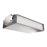
9VH
For 4-pipe fan coil units (VH07) with a hydraulic connection left side, the hot coil is located after the cold
coil, in relation to the direction of the air.However, for units (VH07) on which a straight hydraulic connection
is chosen, the hot battery is located before the cold battery. For 4 tube fan-convector units (VH15/VH18/
VH21/VH24/VH27), the hot battery is always located after the cold battery from the airow point of view.
Valves are not available for model VH27. Valves for models VH07 are supplied mounted, those for models
VH15/VH18/VH21/VH24 are supplied loose without tubing.
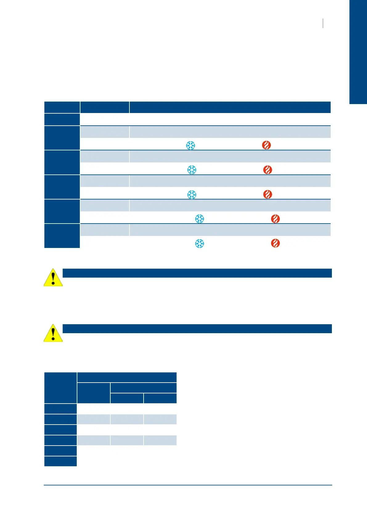
Unit size Version coil connections
VH07
2 & 4 Pipes Female threaded type Ø1/2"
VH15
2 Pipes 2 male threaded end Rc 1"
4 Pipes
2 male threaded end Rc 1"
+ 2 male threaded end Rc 3/4"
VH18
2 Pipes 2 male threaded end Rc 1"1/4
4 Pipes
2 male threaded end Rc 1"
+ 2 male threaded end Rc 3/4"
VH21
2 Pipes 2 male threaded end Rc 1"1/4
4 Pipes
2 male threaded end Rc 1"
+ 2 male threaded end Rc 3/4"
VH24
2 Pipes 2 male threaded endRc 1"1/4
4 Pipes
2 male threaded end Rc 1"1/4
+ 2 male threaded end Rc 3/4"
VH27
2 Pipes 2 male threaded end Rc 1"1/4
4 Pipes
2 male threaded end Rc 1"1/4
+ 2 male threaded end Rc 3/4"
The use of regulation valves (factory-tted, supplied as an accessory or by the client) is mandatory to ensure
that the appliance operates correctly.
7.3. COIL WATER VOLUME
Unit size
Water volume (in liters)
2-pipes
4-pipes
Cooling Heating
VH07
2.3 1.9 0.6
VH15
3.7 3.1 1.0
VH18
5.4 3.7 1.7
VH21
6.5 5.2 1.7
VH24
7.0 5.8 1.7
VH27
8.9 7.3 1.9