English
The unit base shall be arranged as indicated in the manual. There could be a risk of personal injury
or damage to property in the event of the unit being incorrectly supported.
Caution
Do not install the unit in a machinery room or a kitchen where vapours or oil mist could pass
through the unit.
Do not install the unit in a laundry or in very damp areas (bathroom, sauna, etc.).
Caution
A
D
7VH
6.2. UNIT LOCATION
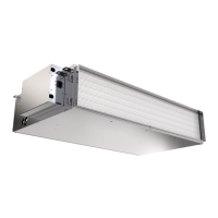
1. The units are designed for installation above a suspended ceiling.
2. Install the unit in a location where the structure is capable of withstanding the weight of the unit.
3. Install the unit in a location which enable the unit's aeraulic inlet and outlet connections to be made.
4. Install the unit in a location providing for easy condensate evacuation.
5. Ensure that there is sufcient free space between the suspended ceiling and the solid ceiling for the
unit to be located.
6. Take care to leave adequate space around the unit for maintenance access (for minimum free space
on the service elevation for access to the lter and the fan motor assembly).
6.3. INSTALLATION INSTRUCTIONS
1. The unit is designed to be suspended on threaded rods or screw-spikes to be supplied by the
installer. The mounting lugs with slot type holes are tted to the upper part of the unit.
2. Attach the 4 threaded rods or spike-screws to the solid ceiling in accordance with the diagram
opposite. Place 4 nuts and washers on each threaded rod.
3. Lift up the unit and slide the 4 threaded rods through the mounting lugs slots (the unit casing must
not touch the ceiling).
4. Attach the unit with 4 further rmly tightened washers, nuts and lock nuts. We recommend tting
rubber blocks to prevent any risks of vibration be transmitted to the structure.
5. Lock the unit in its nal location and level it off with a spirit level in order to guarantee correct
operation and condensate evacuation.
6. The unit must be installed so that the water drains towards the evacuation connection.
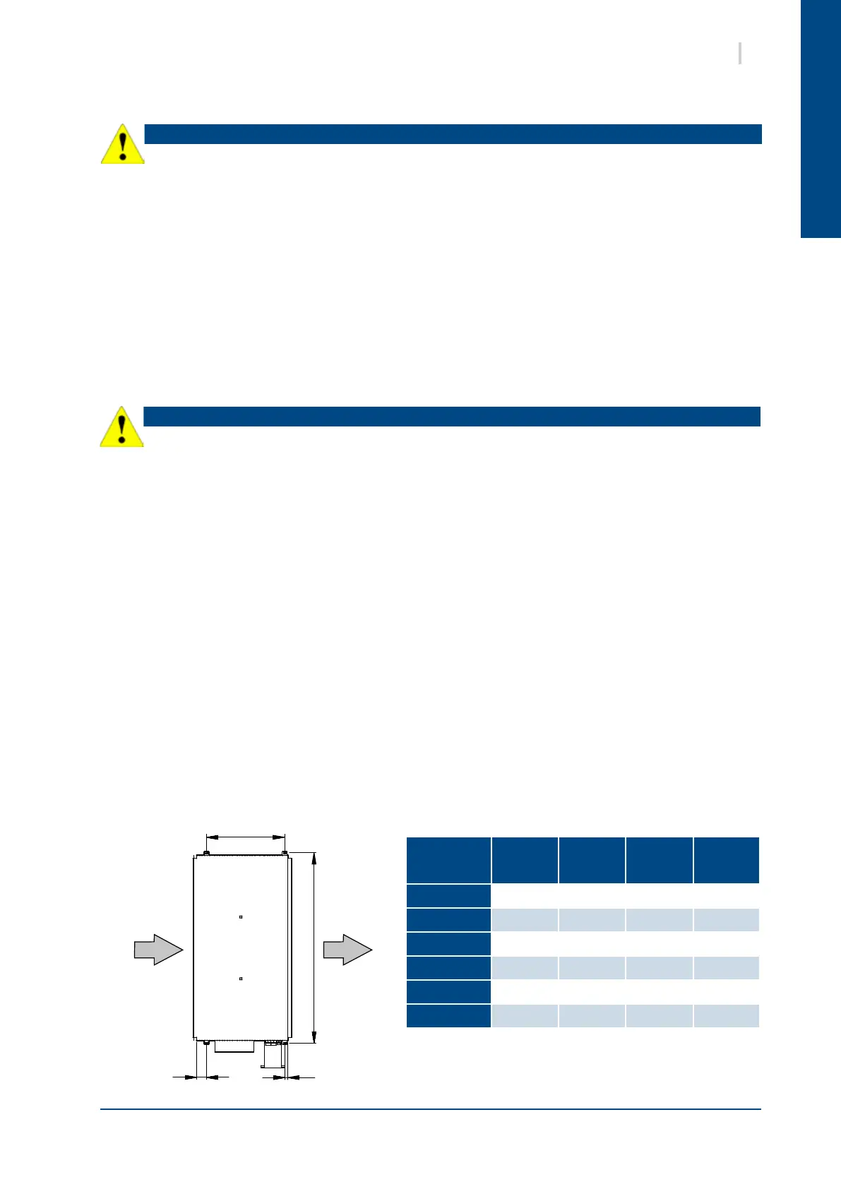
Mounting lugs
TOP VIEW
Unit size
A
(mm)
B
(mm)
C
(mm)
D
(mm)
VH07
1240 41 36 561
VH15
1420 41 36 661
VH18
1420 41 36 661
VH21
1420 41 36 661
VH24
1540 41 31 666
VH27
1540 41 31 666