TAC AB, Feb 2000
4:8
Special functions, P:16 -
TAC 200 User’s Manual
P:32 Max. room influence, day
P:33 Max. room influence, night
System without room sensor
If the DIP-switch (section 2.1) indicates that there is no room sensor, then
there is no adjustment of the control curve. However, the supply temperature
setpoints are parallel displaced when setting the Curve parallel adjustment
(P:08) to a value not equal to zero.
The supply temperature controller uses these parameters.
P:34 Supply P-band (°C)
P:35 Supply I-time (minutes)
The actuator stroke time is set with
P:36 Actuator stroke time (seconds)
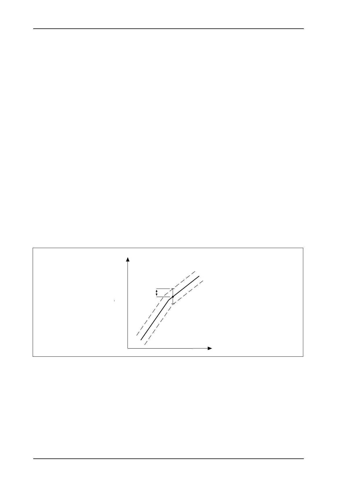
P:66 Hysteresis at on/off control, supply temperature.
On/off is +/– in °C from curve of stage 1, see the figure below.
t
supply
y (°C)
t
outdoor
x (°C)
P66
+
–
When on/off control is used, the delay time in degree-minutes till the next
stage is switched on (or off) is given by
P:37 °C x min On/Off
Ex.: If P:37=15 and the control error is 1°, it will take 15 minutes before the
next stage is changed (1° x 15=15). If the error is 3°, it will take only 5 minutes
(3° x 5=15).
 Loading...