TAC Xenta, TAC Xenta® 400 I/O Modules 3 Technical Description
TAC AB, Dec 2004 19 (48)
0-004-7771-3 (EN)
3.2 TAC Xenta 411/412 Digital Input module
The modules have ten digital inputs, these inputs can also be used as
pulse counters.
The TAC Xenta 412 is also equipped with LED status indicators, one
for each digital input. The LED colors, red or green, can be selected
individually by the setting switches under the front cover.
Terminals (411, 412) and Indicators (412)
Technical data TAC Xenta 411 and 412
Supply voltage (G, G0) .................................24 V AC ±20%, 50/60 Hz
or..........................................................................19–40 V DC
Power consumption.................................................................max. 2 W
Transformer sizing .........................................................................2 VA
Digital inputs (X1–X10):
Quantity........................................................................................10
Voltage across open contact..............................................33 V DC
Current through closed contact ...............................................4 mA
Pulse input duration (TAC Menta CNT block)..............min. 20 ms
LED digital input status indicators (TAC Xenta 412 only):
Quantity........................................................................................10
Color.................................red or green, selected with a DIP switch
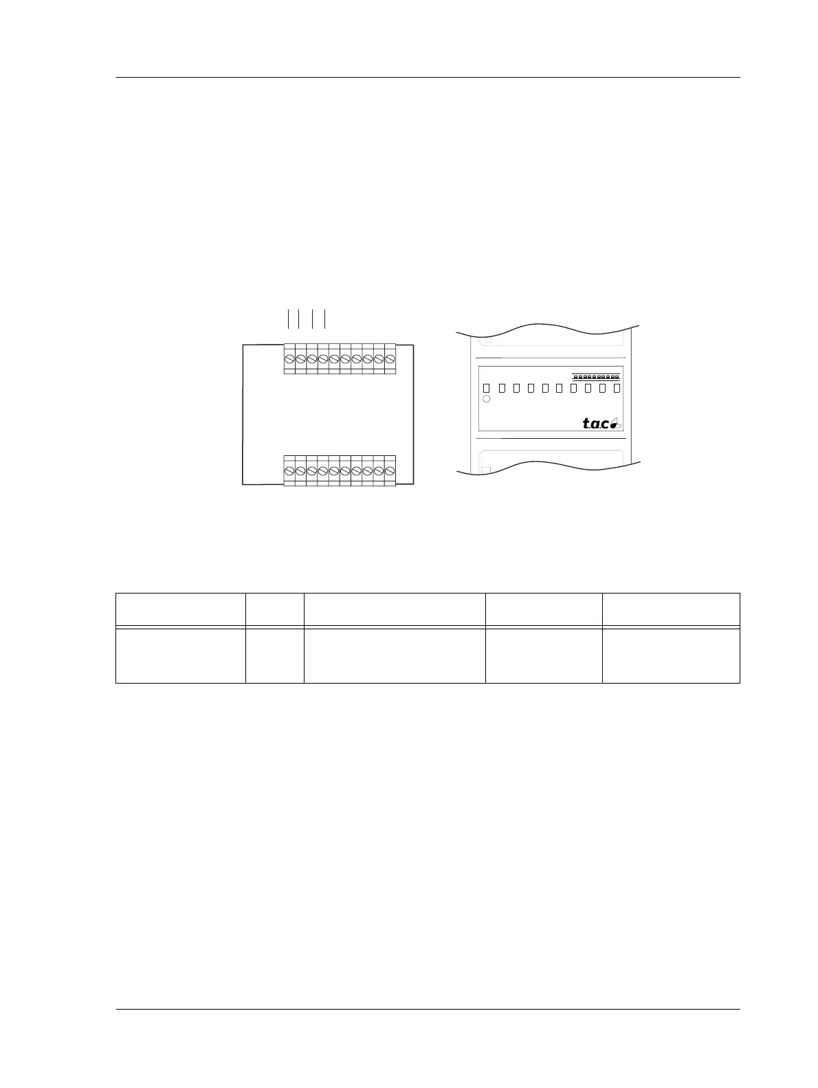
Fig. 3.3: TAC Xenta 411/412 terminals and TAC Xenta 412 DI indicators
2 3 4 5 6 7 8 9 10
DI
TAC Xenta 412
~ 0
24 V AC/DC
}
1 2 3 4 5 6 7 8 9 10
11 12 13 14 15 16 17 18 19 20
X5 M X6 X7 M X8 X9 M X10
G G0 C1C2 X1 M X2 X3 M X4
Comm
}
10 DI Indicators:
⇑ red
⇓ green
Table 3.1: TAC Xenta 411/412 summary
Type No. TAC Menta Block type Terminal ref. Indicators (412)
Digital input 10 DI - Digital input or
CNT - Pulse counter
X1 - X10
X1 - X10
red or green
red or green
 Loading...