4 Installation TAC Xenta, TAC Xenta® 400 I/O Modules
34 (48) TAC AB, Dec 2004
0-004-7771-3 (EN)
4.2 Electrical installation
4.2.1 General considerations
Installation is normally treated as category CAT III (IEC 664), which in
principle means permanent connection to a 230 V AC mains supply. For
the Xenta 400, this is only applicable to the relay outputs of the I/O
modules.
All equipment connected to the TAC Xenta units must comply with the
following standards:
• EN 60 742 (or other relevant safety standard; for example ETL
listing UL 3111-1, first version and CAN/CSA C22.2 No. 1010.1-
92) for the device(s) that provide an ELV-type power supply (nor-
mally 24 V AC) to the controller and other connected equipment.
• EN 61 010 or IEC 950 (or other relevant safety standard) for com-
puters, modems and other equipment powered by a 230 V mains
supply.
If equipment using a 230 V mains supply is connected to a relay output
terminal of the I/O modules, low-voltage equipment connected to the
other relay terminals of the controller must provide at least basic insu-
lation to all touchable parts.
We strongly recommend that switches are installed to make it possible
to separate external equipment when the relay output terminals control
equipment using a 230 V mains supply.
4.2.2 Input/Output Circuit Principles
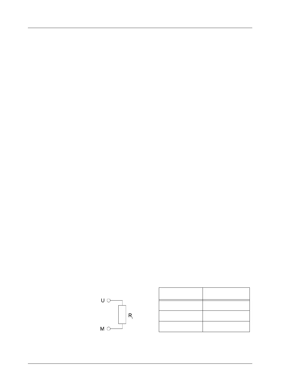
The input/output circuit principles and key values are shown below.
Current Input 0-20 mA
Fig. 4.3: Current Input - internal resistance
Table 4.1:
Unit R
i
ohm
Xenta 420A 47
Xenta 450A 47
Xenta 470 20
 Loading...