11
Interfaces
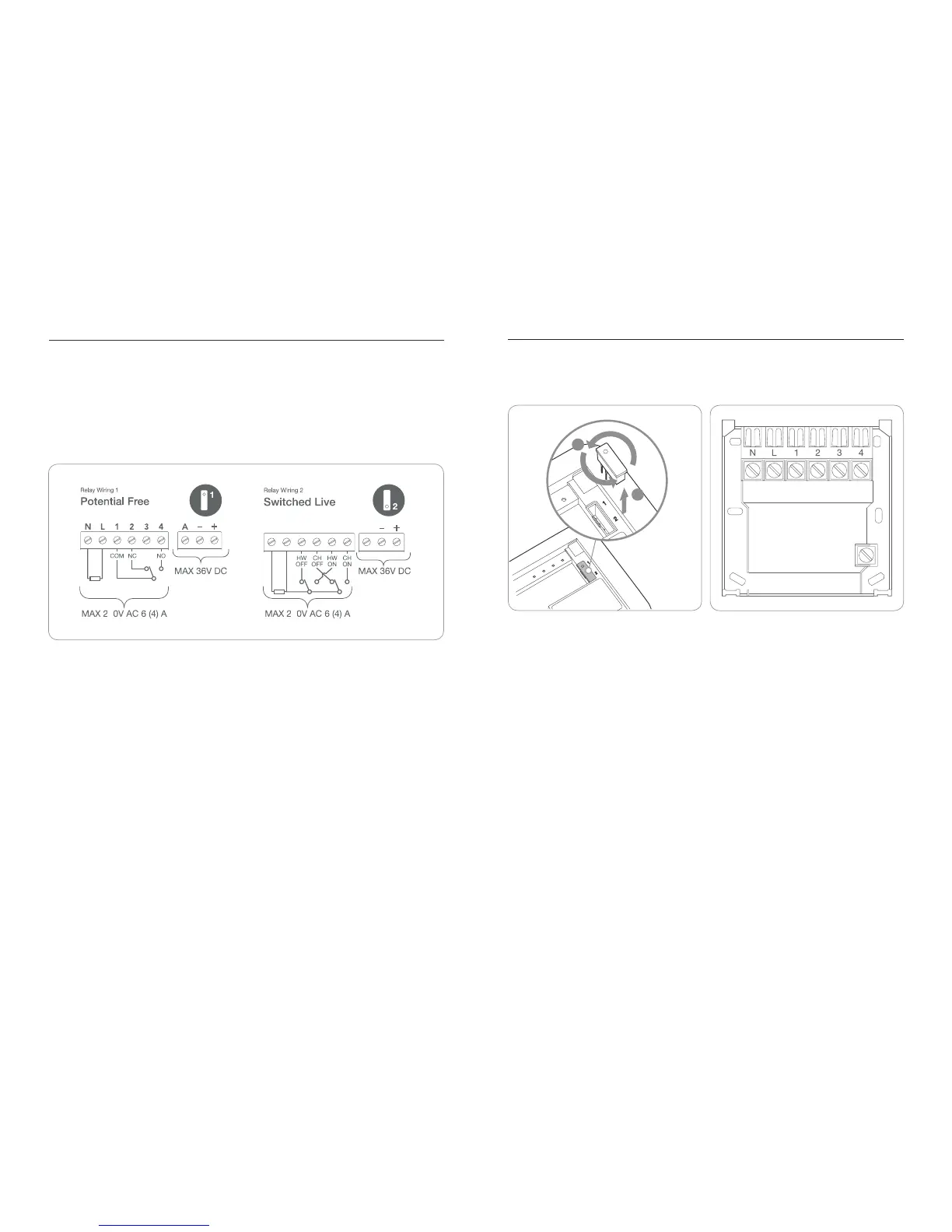
The tado° Extension Box has connectors for relays (labeled 1-4) as well as analog and
digital interfaces (labeled A, -, +). Two relay wiring congurations are possible and are
distinguished by two different jumper positions.
Jumper Position 1: Potential Free Wiring Connection
The power supply is separated from the relays. This wiring option is to connect low
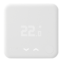
voltage single relays. In case a UK standard backplate is present some rewiring might
be required such that the wires correspond to tado°‘s “Relay Wiring 1” as indicated on
the back of the Extension Box.
Jumper Position 2: Switched Live
This wiring option corresponds to a 230V dual relay programmer. In case a UK stan-
dard backplate is present and wired as a 230V dual relay (central heating and hot
water) the tado° Extension Box can simply be mounted on the existing backplate and
does not require any rewiring.
Extension Box – Interfaces
3 3
NLNL 1212 3434
A
2
1
Relay Wiring Diagrams
UK Standard BackplateSwitching the Jumper Position
Analog and Digital Connection
To connect an analog thermostat, the analog output is connected to “A”, ground
(GND) to “-” and the positive input (Vcc) to “+”.
To connect a two-wired digital thermostat, the two extra low voltage terminals labeled
with “-” and “+” are used. Digital bus interfaces are typically protected against polarity
reversal, thus the order of connection does not matter.