CNC-110A Series C-03/C-13 User's manual
9
έᚊཝҋજѣࢨΦ
TAILY AUTOMATION CO.,LTD.
MAX
:
Maximum winding speed.
1. Rotate H.S. and L.S. potentiometer on back panel, to the right end [H].
Then press key to start winding in high speed, and press key to change the TURNS
DISPLAY shows winding speed (RPM).
2. Rotate MAX to make the winding speed (RPM) as you want.
Then press key to stop winding.
8.2. External Connection Model (CNC-110AE)
Winding spindle control mode selection
.
Select by JP1 (see Figure-1 or Figure-3).
There are two control mode can be select.
1.
1C
:
The
CN5-pin2
represent winding
(RUN)
output. The
CN5-pin3
represents winding
direction
(DIR)
output.
2.
2C
:
The
CN5-pin2
represent
clockwise
(CW)
output. The
CN5-pin3
represents
counter-clockwise
(CCW)
output.
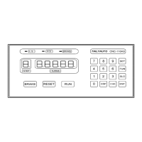
9. FUNCTION TABLE
Set –up winding parameters
:
--------- .
Select first memory group
:
------------ .
Select second memory group
:
------- .
Select third memory group
:
----------- .
With zero point
:
-------------------------- .
Without zero point
:
---------------------- .
Single brake mode
:
--------------------- .
Double brake mode
:
-------------------- .
Relative counting mode
:
--------------- .
Absolute counting mode
:
-------------- .
ON-OFF mode
:
-------------------------- .
TRIGGER mode
:
------------------------ .
Counting unit = 1
:
----------------------- .
Counting unit = 0.1
:
--------------------- .
Set-up braking action time
:
----------- .
Set-up slow start turns
:
---------------- .
Brake off
:
---------------------------------- .
Brake on
:
---------------------------------- .
Clear all memory
:
----------------------- .
 Loading...