Do you have a question about the TAILY AUTOMATION CNC-210A and is the answer not in the manual?
Controls the AC power supply to the controller.
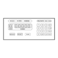
Detailed explanation of each key's function on the front panel.
Details the meaning and display of digital indicators on the front panel.
Explains the status indicated by various LEDs on the front panel.
Defines the parameters used for winding operations and their ranges.
How to define memory regions for storing winding parameters.
Guide to programming specific winding parameters for each step.
Procedure for setting the guiding traverse shaft location and limits.
Instructions on how to clear all programmed winding parameters.
Details absolute and relative counting modes for winding turns.
Describes interlace and non-wire guiding methods.
Explains single-click and double-click operation modes.
Details continual, edges slow, and automatic circular running modes.
Methods for accurately setting winding turns using preset and speed adjustments.
Procedure for starting, pausing, continuing, and resetting the winding process.
How to switch data display between turns and traverse position.
How to view spindle shaft RPM instead of piece count.
Managing the piece counter, including preset and reset functions.
Configures winding mode settings like speed, counting, and braking.
Setting the unique station number for RS-485 communication.
Setting or entering a password to protect configuration data.
Setting the maximum travel distance for the guiding traverse.
Configures how often the guiding traverse corrects its location.
Limits winding speed to ensure synchronization with traverse.
Sets the duration for which the brake is held.
Selects the speed for guiding traverse movement to start/home positions.
Selects output mode for CNC-210AS and CNC-210AE.
Sets acceleration and deceleration times for the winding spindle.
Resets all configuration data to factory initial values.
Transmits winding data and settings to other stations.
Lists available accessories and options for the controller models.
Provides wiring diagrams for connectors CN2 through CN6.
Details the specific wiring connections for the CNC-210AS model.
Details the specific wiring connections for the CNC-210AE model.
Covers output current limit, torque compensation, and max speed adjustments.
Covers speed mode selection and V-out adjustment for CNC-210AE.
Illustrates the internal wiring connections between controller components.
Guidelines for regular cleaning and checking of controller parts.
Lists and explains various error messages and their meanings.
Procedure to abort seeking original position during boot or reset.
Provides troubleshooting procedures for common operational faults.
| Model | CNC-210A |
|---|---|
| Brand | TAILY AUTOMATION |
| Control System | TAILY AUTOMATION CNC system |
| Control Mode | G code |
| Display | 7-inch color LCD |
| Program Memory | 64MB |
| Input Voltage | AC 220V±10% 50Hz/60Hz |
| Power Consumption | ≤50W |
| Operating Temperature | 0℃~45℃ |
| Storage Temperature | -20℃~60℃ |
| Humidity | 40%~80% |
| Communication Interface | USB |
| Dimensions | 280mm×190mm×70mm |
| Weight | 2kg |