CNC-210A Series H6681 User manual
Page
12
of 20
έᚊཝҋજѣࢨΦ
TAILY AUTOMATION CO.,LTD.
8. INSTALLATION AND WIRING
The controllers should be operated in an environment that is protected from moisture,
corrosive gases, or liquid, and free from airborne dust, metallic particles, and magnetic noise.
Do not block the intake/exhaust ports of the controller. Otherwise, a fault may occur.
Make sure that the power source supplies the correct voltage and is capable of supplying the
required current to the controllers.
Do not connect or disconnect wires and connectors while power is applied to the controller.
Make sure the machine and controllers are properly grounded.
Make sure that the leads and connectors are connected correctly.
Normally operate under 10
℃
~ 40
℃
environment; over 40
℃
should perform under good
ventilation, avoid heating.
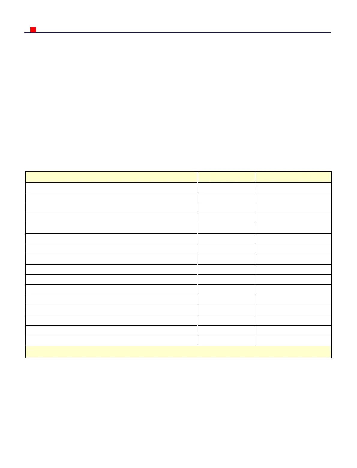
8.1. Accessories and options
NAME CNC-210AS CNC-210AE
210A-CN2 RS-485 Connection box
○ ○
210A-CN3 O
erate switches connection cable
○ ○
210A-CN4 Home sensor connection cable
○ ○
210A-CN5 Countin
sensor connection cable
○ ○
210A-CN6
ux I/O si
nal connection cable
○ ○
210A-CN7 Pulse out
ut connection cable
× ○
210A-CN8
C out
ut connection cable
× ○
HOME-SR Home senso
○ ○
CNTB-03B/C Countin
senso
○ ○
DISC Countin
disc
○ ○
START Push button switch
○ ○
STOP Push button switch
○ ○
RESET Push button switch
○ ○
Foot switch RUN/STOP Foot switch
○ ○
Power cord
C Power cord
○ ○
×
= not use in this model
 Loading...