CNC-210A Series H6681 User manual
Page
13
of 20
έᚊཝҋજѣࢨΦ
TAILY AUTOMATION CO.,LTD.
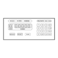
8.2. Wiring diagram for CN2~CN6
STOP START RESET
CNTB-03B
Turn CounterHome Sensor
1
1
2
34
ab
RS-485
Connection Box
1
2
FOOT SW
HOME-SR
CN2 CN3 CN4 CN5 CN6
RESET
Operate Switches
+24V
START
STOP
LAMP3
LAMP2
LAMP1
IP6
C0M
HOME
IP5
+24V
PHC
C0M
PHB
PHA
+24V
IP2
IP1
IP3
IP4
COM
OP1
+24V
OP2
OP3
OP4
TR-
TR+
RS-485 Home Sensor Turn Counter AUX I/O
CN5CN4
1
CN3
CN7
Pulse Output
0V
DIR
PUS
+5V
Operate Switches
12
34
ab
12
34
ab
IP1
IP2
IP3
IP4
COM
+
+
+
+
OP1
OP2
OP3
OP4
+24V
AUX I/O
CN6
IP5
IP6
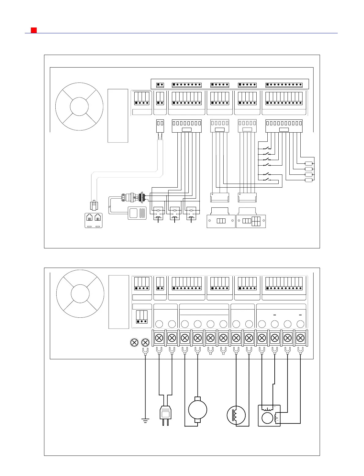
8.3. Wiring diagram for CNC-210AS
GND
M
AA
B
B
11 12
ACAC BK+BK-AABB
COM CW CCW
F-HF+
Vout
10987654321
AC Input Winding Driver Brake STEP MotorCN8
CN7 CN2 CN3 CN4 CN5 CN6
RESET
Operate Switches
+24V
START
STOP
LAMP3
LAMP2
LAMP1
IP6
C0M
HOME
IP5
+24V
PHC
C0M
PHB
PHA
+24V
IP2
IP1
IP3
IP4
COM
OP1
+24V
OP2
OP3
OP4
TR-
TR+
RS-485Pulse Output Home Sensor Turn Counter AUX I/O
AC Output
0V
DIR
PUS
+5V
AC
GND
AC
A
EARTH AC Input
Brake
DC24V 12WWinding Spindle
Guiding Traverse
2Phase
6V 2A
STEP Motor
Motor
 Loading...