10 Safety and Regulatory Warnings TM9300/TM9400 Installation Guide
© Tait Limited December 2015
1.9 Non-standard Radio Installations
The installation U-cradle described in this guide has been designed so that
there is enough airflow around the radio to provide cooling.
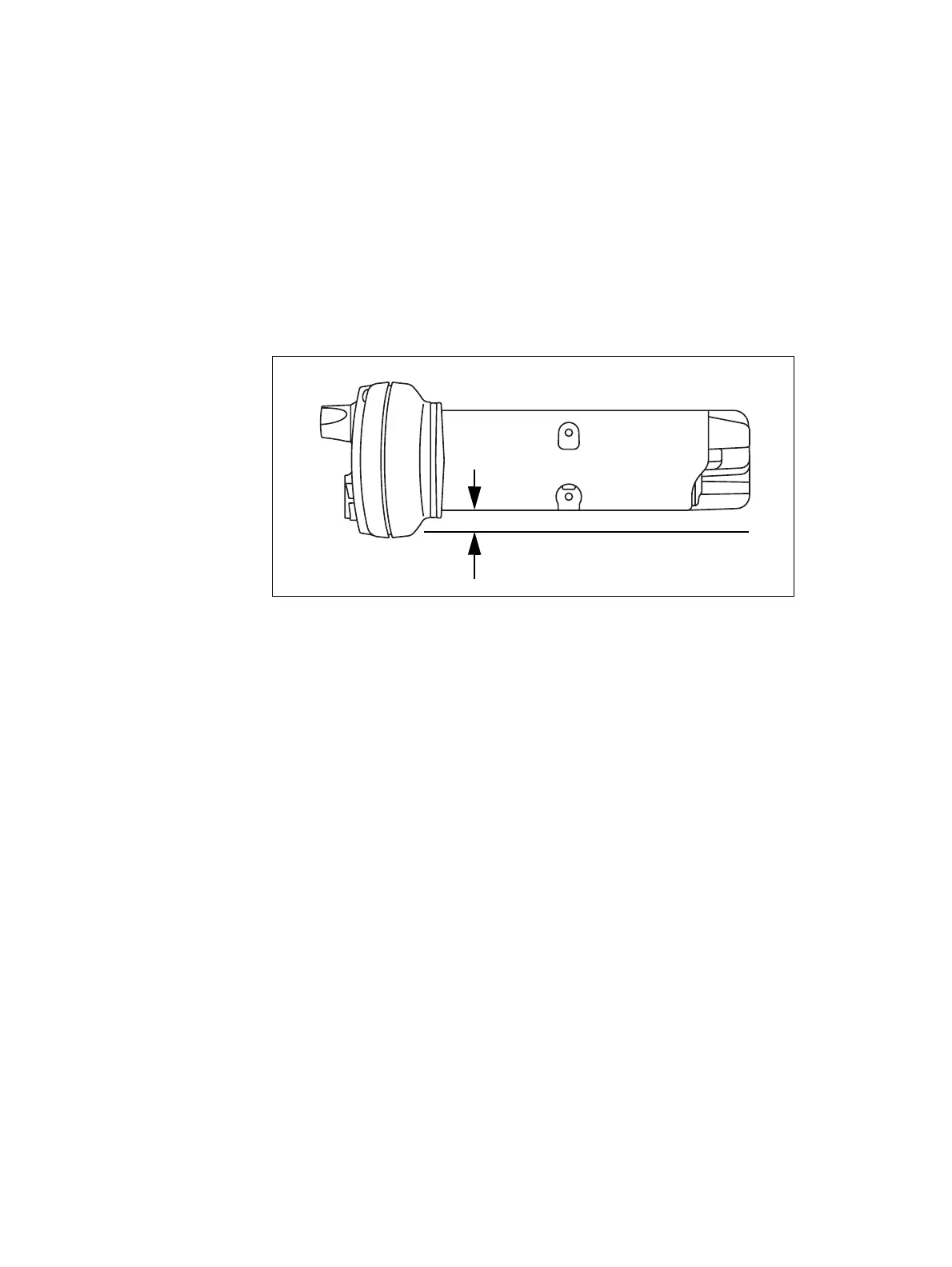
If a non-standard installation method is used, care must be taken that
sufficient heat can be dissipated from the heatsink fins and the ridged
bottom surface of the radio.
For this to be achieved, there must be a gap of more than 3/8 inch (10 mm)
between the bottom surface of the radio chassis and the mounting surface.
This is illustrated in the following diagram:
1.10 Negative Earth Supply
The radios are designed to operate only in a negative earth system.
3/8 inch (10 mm)
mounting surface

 Loading...


