25
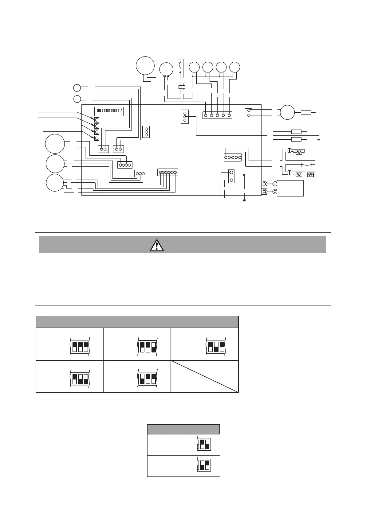
18. WIRING DIAGRAM
19. DIP SWITCH SETTINGS
WARNING
•
• Only change the switches with dark squares.
• DO NOT adjust other switches.
•
W··· WHITE
R· · · RED
BK···BLACK
P···PURPLE
BL· · · BLUE
G· · · GREEN
Y··· YELLOW
O···ORANGE
BR···BROWN
Igniter rod
BK
BK
BK
BL
R
R
R
Y
O
W
R
W
R
G
G
G
Y
O
O
P
P
W
W W
BK
53
9
73
3
ON
12345678910
MAX button
MIN button
Increase button
Decrease button
Inlet
thermistor
Outlet
thermistor
Gas
propor-
tional
valve
Flow
sensor
Flow
adjust
valve
Ground
Hi-
limit
Ground
240 VAC
Air-fuel ratio rod
Flame rod
Remote
controller
O.H.C.F
Heater
Heater
Thermostat
IG
FM
PCB
SV3MV SV1 SV2
BK
BK
BL
BL
BL
BL
BL
BR
BL
BL
BL
BL
40°C
60°C MODEL
DEFAULT
60°C
45°C
55°C
Temperature settings
50°C MODEL
DEFAULT
50°C
OFF
ON
TMP1
TMP2
TMP3
8 7 6
TMP1
TMP2
TMP3
OFF
ON
8 7 6
TMP1
TMP2
TMP3
OFF
ON
8 7 6
TMP1
TMP2
TMP3
OFF
ON
8 7 6
TMP1
TMP2
TMP3
OFF
ON
8 7 6
OFF
ON
OFF
ON
2 1
2 1
Propane
Universal LPG
Natural
Gas
Gas type
the switches.
*NOTE:
 Loading...