3. MAINTENANCE
IOM manual Tapflo Metal Series 21
3.6. Aluminium and cast iron – Assembly of the pump
The assembly procedure is done in the reverse order to the disassembly.
Nevertheless there are a few things that you have to remember in order to assemble the
pump correctly.
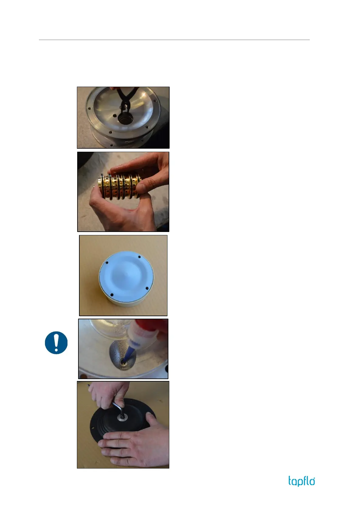
Fig. 3.6.1
Before inserting the air valve [61], insert the circlip
[27] on one side of the centre block [12].
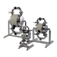
Fig. 3.6.2
When putting the air valve [61] into the centre block
[12], apply some water or alcohol on the
O-rings to provide smooth insertion of the air valve.
It is recommended to use a pressing device for this
operation.
ATTENTION! When inserting the TX25 size air valve,
replace the shaft with a screw and a nut to make sure
the air valve assembly remains properly fastened.
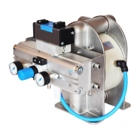
Fig. 3.6.3
When screwing in the diaphragms [15] on the shaft
[16], the holes in the diaphragms must align with the
holes in the centre block [12]. Sometimes it is
necessary to turn the diaphragm back a little bit in
order to align the holes.
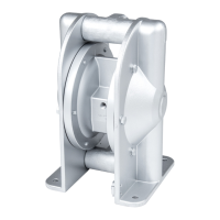
Fig. 3.6.4
Apply some Loctite 243 on the thread before
screwing in of the valve ball stops [22].
ATTENTION! Make sure the glue is inserted on the
thread and not only on the bottom surface of the
orifice.
Fig. 3.6.5
When assembling the diaphragms [15], the first step
is to screw the grub screw into one of the diaphragms
as much as possible.