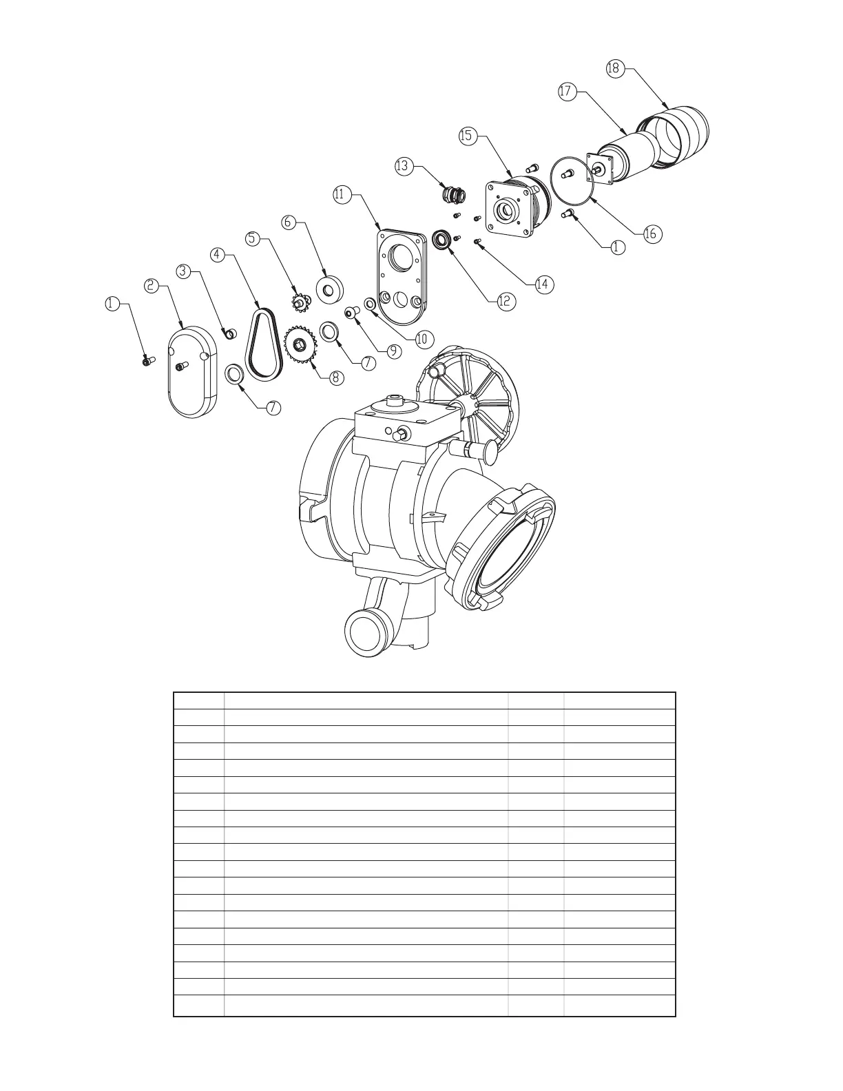
1 1/4-28 X 5/8 SOCKET HEAD CAP SCREW 6 VT25-28SH625
2 REDUCER COVER 1 A1097
3 BUSHING NYLON 1 X252
4 38LINK ROLLER CHAIN 1 AX1685
5 DRIVE SPROCKET 12 TEETH 1 X253
6 BUSHING MOTOR 1 X256
7 THIN WASHER 2 A1530
8 BIV SPROCKET 25 TEETH 1 A1098
9 3/8-16 X 3/4 BUTTON HEAD CAP SCREW 1 VT37-16BH750
10 LOCK WASHER 3/8" 1 VW375SSLOCK
11 REDUCER HOUSING 1 A1096
12 CUP SEAL 1.0625 X .5625 X 1/4 1 Y4620
13 STRAIN RELIEF PG11 .39 HOLE 1 Y5205
14 6-32 X 5/16 LONG SHCS WITH HEAD SEAL 4 VT06S32SH312
15 MOTOR SOCKET 1 Y4615
16 O-RING-038 2-5/8 ID 1/16 C/S 1 VO-038
17 GEAR MOTOR WITH ENCODER 1 Y4610
18 ENCLOSURE 1 Y4616
INDEX DESCRIPTION QTY PART #
8.0 DRAWINGS AND PARTS LISTS
11
©Copyright Task Force Tips, Inc. 2002-2006
Exploded View
of Motor Assembly for
Ball Intake Valve RC and
Jumbo Ball Intake Valve RC