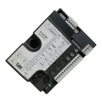
ENGLISH
9 - 11 CLOSE
CLOSE button N.O. input – Controls the total closure of the
bar. (9 = CLOSE - 11 = COM)
10 - 11 PHOTOCELLS
N.C. photocell input - it cuts in during the closing or the open-
ing manoeuvre, see dip-switch no. 3. (10 = FOT - 11 = COM)
Note: the photocell transmitter must always be supplied
by terminals no. 3 and no. 4, since the safety system test
(phototest) is carried out on it. Without this connection,
the control unit does not work. To override the testing of
the safety system, or when the photocells are not used,
set dip-switch no. 6 to OFF.
12 - 13 STOP
STOP button N.C. input – Stops the bar in any position,
temporarily preventing the automatic closure, if programmed.
(12 = COM - 13 = STOP)
12 - 14 OPEN/CLOSE
OPEN/CLOSE button N.O. input – Controls the opening and
closing of the bar and is regulated based on the function of
dip-switches 2 and 4. ( 12 = COM - 14 = O/C)
12 - 15 OPEN
OPEN button N.O. input – Controls the total opening of the
bar. (12 = COM - 15 = OPEN)
16 - 17 AERIAL
plug-in radio-receiver aerial input , for 40.665 MHz receivers
only. (16 = SIGNAL - 17 = GROUND)
18 - 19 2
nd
CH RADIO
2
nd
radio channel output - for control of an additional automa-
tion or for switching on lights, etc... (N.O. clean contact)
Warning: to connect other devices to the 2nd Radio
Channel (area lighting, pumps, etc.), use an additional
auxiliary relay (see note at end of paragraph).
20 - 21 - 22 ENCODER
encoder supply and input. (20 = BROWN positive - 21 =
WHITE signal - 22 = BLUE negative);
23 - 24 MOTOR
motor supply output 18 V DC max. 50 W.
(23 = POSITIVE - 24 = NEGATIVE)
FS1 - FS2 POWER SUPPLY
13,5 V AC control unit power supply input – Fed by the toroi-
dal transformer and protected by the fuses on the 230 V AC
power supply.
IMPORTANT:
• Do not connect auxiliary relays or other devices tot he 18 V DC output (terminals 1 – 2)
to avoid malfunctions of the control unit. Use separated power supply / transformers
instead;
• do not connect switching feeders or similar apparatus close to the barrier that may be
a source of disturbance;
MEMORIZATION PROCEDURE
WARNING: After powering the control panel, wait 2 seconds before you start performing
the adjustment operations.
Note: the mechanical stops of the bar must be regulated both in opening and in closing
[see RBL and CITY instructions].
When you have completed the installation procedures :
1_ place the bar at approx. 45°;
2_ set dip-switch no. 8 to ON;
3_ control the automation with one of the following inputs: O/C, radio control or control unit but-
ton.