16
- do not re-use old pre-existing cables;
2. INTRODUCTION
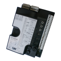
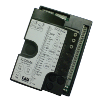
The K206MA board has two working modes, selectable through the J6 jumper (see wiring diagram).
J6 Jumped: standard mode, i.e. the control unit is powered all the time;
J6 Not jumped: low-energy mode, i.e. the control unit is switched o after each operation and on
after each command (mode where power is supplied by other energy sources,
ex. batteries charged by a photovoltaic panel).
Once the connection is achieved, in low-energy mode, press the PROG button briey:
• All the green LEDs must be on (each of them corresponds to a Normally Closed input). The go o
only when the controls to which they are associated are operated. Except for the green led DL4,
which corresponds to CLOSE input (a Normally Open contact).
• All the red LEDs (and the green led DL4) must be o (each of them corresponds to a Normally Open
input). The light up only when the controls to which they are associated are operated.
3. TECHNICAL CHARACTERISTICS
Board power supply 13,5V AC - 50 Hz
Max. absorption DC motor 14 Ah - 18V DC
Fast acting fuse for protection of input power supply 13,5V AC (F4 - 5x20) F 16A
Fast acting fuse for battery charger protection (F5 - 5x20) F 10A
Fast acting fuse for protection of auxiliary circuits 18V DC (F3 - 5x20) F 3.15A
Motor power supply circuits voltage 18V DC
Auxiliary device circuits supply voltage 18V DC
Logic circuits supply voltages 5V DC
Operating temperature -20 °C ÷ +55 °C
4. CONNECTIONS TO TERMINAL BOARD
Terminals Function Description
FS1 - FS2
POWER
SUPPLY
13,5V AC control unit power supply input – Fed by the toroidal trans-
former and protected by the fuses on the 230V AC power supply.
1 - 2 AUX INPUT
external power input (ex. Photovoltaic system 12V DC).
NB: In the latest versions of the control boards, the voltage change
through jumper J7 is no longer necessary (make sure whether it is
present on the control board or not).
ATTENTION: POWERING THE CONTROL UNIT WITH AN EXTERNAL
SOURCE, ALL THE OTHER 18V DC OUTPUTS BECOME THE SAME AS THE
OUTSIDE VOLTAGE.
3 - 6 OPEN
OPEN button N.O. input – Controls the total opening of the barrier.
(3= OPEN - 6= COM)
4 - 6 OPEN/CLOSE
OPEN/CLOSE button N.O. input – Controls the opening and closing of the
barrier and is regulated based on the function of dip-switches 2 and 4.
(4= O/C - 6= COM)
5 - 6 STOP
STOP button N.C. input – Stops the bar in any position, temporarily pre-
venting the automatic closure, if programmed. Bridge the connectors if
not used. (5= STOP - 6= COM )
7 - 8 CLOSE
CLOSE button N.O. input – Controls the total closure of the barrier.
(7= COM - 8= CLOSE)
ENGLISH
 Loading...