8
TAU Srl
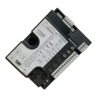
K550M
TRIMMER LOGIC ADJUSTMENT
T.L. Operating time adjustment: from 5 to 120 seconds. The trimmer is set to about 10 seconds longer than
it takes the gate to open.
T.C.A. Automatic closing time adjustment from 5 to 120 seconds.
R.C.M. Motor torque adjustment. The trimmer is set to provide suffi cient thrust to work the gate without
exceeding the limits established by current standards.
J 1 When the jumper is open, maximum starting thrust does not exceed 400Nm, in compliance with EN
12453. When the jumper is closed, maximum starting thrust equals the true capacity of the gear motor
(used for non-EEC markets).
PROGRAMMING DIP SWITCHES
N°1 ON: after opening, the gate automatically closes when the delay set on the T.C.A. trimmer expires.
OFF: automatic closing disabled.
N°2 ON: with automatic closing enabled, a sequence of open/close commands causes the gate to
OPENCLOSE-OPEN-CLOSE etc (see also dip switch 4).
OFF: in the same conditions, the same command sequence causes the gate to OPEN-STOP-
CLOSESTOP-OPEN-STOP (step-by-step).
N°3 ON: during opening, the photocell cuts in to stop the gate until the obstacle is removed. During closing,
it stops the gate and totally opens it when the obstacle has been removed.
OFF: during opening, the photocell does not cut in; while during closing, it behaves as if the dip-switch
were in the ON position.
N°4 ON: the open-close pushbutton reverses the direction of movement of the gate even while it is
opening.
OFF: the direction of movement is only changed during closing.
N°5 ON: opening and closing only with pushbuttons.
OFF: timer connection enabled for pre-set opening and closing (see attachment).
N°6 ON: the pre-fl ashing and photocell test function enabled.
OFF: the pre-fl ashing and photocell check function disabled.
Clock function:
For the clock function (dip-switch n° 4 OFF) connect the N.O. contact in parallel with the OPEN / CLOSE contact
(terminals 9 - 12).
TESTING
Once the panel has been connected, the red power on LED L1 must be on, while the red LED’s L7 and L8 must
both be off (each corresponds to a normally open contact). They only light up when the relative command is
enabled. The green LED’s L2, L3, L4, L5 and L6 must all be on (each one corresponds to a normally closed
contact) and only turn off when the relative contact is opened.
LED L1 = power on panel
LED L2 = photocell signal
LED L3 = fi xed edge signal
LED L4 = closing limit switch signal
LED L5 = opening limit switch signal
LED L6 = stop pushbutton signal
LED L7 = pedestrian access signal
LED L8 = open/close pushbutton signal
USING THE BUILT-IN 433.92 MHz RECEIVER
The built-in 433.92 MHz receiver works with the TXD and BUG series of radio-controls and features dip-switch
code programming (max 1 code).
Press button T1 and then the button on the radio control to teach the K550M receiver the code of the radio
control. The panel confi rms it has learnt the code by opening and closing the gate.
Note: by introducing a new code the old code is automatically cancelled.
 Loading...