7
TAU Srl
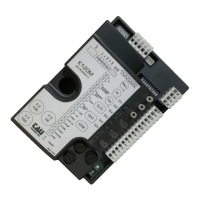
K550M
THE EQUIPMENT MUST BE INSTALLED “EXPERTLY” BY QUALIFIED PERSONNEL AS REQUIRED BY LAW
46/90.
N.B.: It is compulsory to earth the system and to observe the safety regulations that are in force in each
country.
IF THESE ABOVE INSTRUCTION ARE NOT FOLLOWED IT COULD PREJUDICE THE PROPER WORKING
ORDER OF THE EQUIPMENT AND CREATE HAZARDOUS SITUATIONS FOR PEOPLE. FOR THIS REASON
THE “MANUFACTURER” DECLINES ALL RESPONSABILITY FOR ANY MALFUNCTIONING AND DAMAGES
THUS RESULTING.
The K550M panel features an electronic photocell control system which switches the photocell
transmitter on and off thereby causing the control unit microprocessor to check whether the receiver
relay switches correctly. If this does not happen, the control unit is automatically blocked.
- ELECTRONIC CONTROL OF PHOTOCELL SAFETY DEVICES
- MICROPROCESSOR-CONTROLLED LOGIC
- INPUT STATUS LED’S
- LINE INPUT FUSE
- “PEDESTRIAN ACCESS” FUNCTION
- BUILT-IN FLASHING LIGHT CIRCUIT
- OP/CL TIMER SETTINGS
- BUILT-IN 433.92 MHz SELF-LEARNING RECEIVER
- RECEIVER CONNECTOR
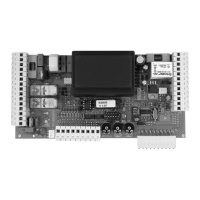
TERMINAL BOARD CONNECTIONS
1 – 2 – 3 POWER input 230 Vac 50Hz (115 Vac 60 Hz). 1=NEUTRAL 2=EARTH 3=PHASE
4 – 5 FLASHING LIGHT output 230 Vac 50 W max. The signal is already modulated for direct use.
Flashing frequency increases slightly during closing
6 – 7 – 8 MOTOR output single-phase 230 Vac common=8; opening=6; closing=7; connect the capacitor
between terminals 6 and 7.
9 –12 OPEN/CLOSE pushbutton input (Normally Open contact);
refer to functions of dip switches n° 4 and n° 2 (12=Common).
10 – 12 PEDESTRIAN pushbutton input (Normally Open contact);
similar to the OPEN/CLOSE pushbutton but only travels about 1 m; used to control pedestrian traffi c
(12=Common).
11 – 12 STOP pushbutton input (Normally Closed contact);
Stops the gate. (12=Common).
13 – 14 OPEN LIMIT SWITCH input (Normally Closed contact); 13=Common.
13 – 15 CLOSE LIMIT SWITCH input (Normally Closed contact); 13=Common.
13 – 16 FIXED SAFETY EDGE input (Normally Closed contact);
Works only when the gate is opening; temporarily stops the gate and partially closes it by about 20
cm in order to allow the obstacle to be removed. (13=Common).
13 – 17 PHOTOCELL OR SAFETY DEVICES input (Normally Closed contact);
They stop the gate during closing and totally reopen it; they temporarily stop the gate during opening
in order to allow the obstacle to be removed (if dip switch n° 3 set to ON), (13=Common).
N.B.: the photocell transmitter must always be connected (terminals 26-27) as it is checked
by the safety system; the control unit will not work if it is disconnected. To disable the safety
system move dip switch n° 6 to OFF.
18 – 19 built-in RX aerial input; 18=EARTH 19=SIGNAL
20 – 21 2nd RADIO CHANNEL output used with auxiliary two-channel receiver for opening/closing another
gate or controlling garden illumination.
22 – 23 push-in RX AERIAL 22=SIGNAL 23=EARTH
24 – 25 GATE OPEN LED output 24 Vac 3 W; the LED fl ashes slowly during opening, remains on when the
gate is open and fl ashes rapidly during closing.
26 – 27 24 Vac 10 W POWER output for PHOTOCELL TX max. no. 1 photocell transmitter.
28 – 29 24 Vac 10 W POWER output for PHOTOCELL RX, EXTERNAL RECEIVERS, etc.
English
 Loading...