45
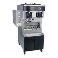
Model C602
Systems, Controls and Operations
040608
Universal Control (UVC3)
The Universal control is the command center for the
machine. The software program, including multiple
language selections, resides in the EPROM chip.
The settings in the menus are saved in the RAM
chip. Removing and reinstalling the RAM chip will
restore the factory default settings in the menus.
The RAM chip must be inserted with the notch
towards the side of the socket with the notch.
Power is supplied to the 5 VDC terminal on the
UVC3 board from the interface board. The operating
voltage range for the control is 4.75 – 5.25 VDC.
Note: For installations with low voltage supply
(210V or less) it may be necessary to wire the 16
VAC transformer on the low voltage tap. Low
voltage supplied to the interface board, in turn
reduces the voltage supplied to the UVC3 board and
may cause intermittent power failure tripping or the
control panel keys do not function when the machine
is powered.
The UVC3 communicates with the control panel
interface board through a USB Cable.
There are three sets of pins on the UVC3 board.
Refer to the following chart to identify their function.
Note: Use Part No. 040084-001 CONNECTOR-
PROGRAMING SHUNT to jumper pins.
JUMPER
UVC3 PINS FUNCTION
Jumper installed -- normal applications using refrigerated mix.
JP1
Pins 1 & 2
No jumper installed -- general market configuration using non--refrigerated mix.
Ignores hopper temperature lockout parameters to allow adding non--refrigerated
mix into the hopper.
Pins 3 & 4 No jumper -- Not used (for future development)
Domestic configuration -- jumper installed. Hopper temperature not displayed
on screen. Heat symbol keys are only active when a lockout condition has
occurred. Standby keys are disabled.
JP2
Pins 1 & 2
International configuration -- no jumper. Hopper temperature is displayed on
screen. Manual heat cycle starts by selecting HEAT symbol. Standby keys are
functional.
Pins 3 & 4 No jumper -- Not used (for future development)
Pins 1 & 2 Jumper installed -- enables audible device located on UVC3 control. Disabled (no
jumper) in models that have an audible device on the control panel board.
Pins 3 & 4 No jumper -- Not used (for future development)