51
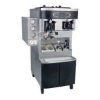
Model C602
Systems, Controls and Operations
Power Switch On / Mod e Select: AUTO
Heat Cycle Activated
From the terminal marked L1 on the interface board,
L1 power is sent to terminal J6 and directed through
the following pins:
Shake Sid e
7 for the beater motor contactor coil (passes through
the beater interlock relay)
4 for the left glycol solenoid.
(Operation of the solenoid is controlled by the shake
product thermistor probes which are connected to
terminal J10.)
3 for the glycol heater relay coil
2 for the glycol pump.
Soft Serve Side
7 for the beater motor contactor coil (after the
freezing cylinder has reached 135°F / 57°C).
(Note: Power must go through the beater interlock
before reaching the coil.)
6 for the agitator motor
4 for the glycol solenoid
(Operation of this solenoid is controlled by the soft
serve glycol thermistor probe which is connected to
terminal J10.)
Operation of the glycol heater is controlled by the
glycol thermistor probe which is connected to
terminal J10 of the shake interface board.
At the completion of the Heat and Hold phases of
the Heat Treatment cycle, the glycol heater stops,
and the main compressors are activated from
terminal J6 pin 1 on the interface boards.
Once the freezing cylinder and hopper thermistor
probes (connected to terminal J10 on the interface
board) have been satisfied, the Heat Treatment
cycle will end.