5
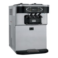
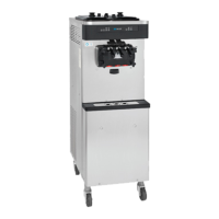
Models C706 & C707
Introduction
Installation Instructions
Air Cooled Units
A minimum of 6” (152 mm) air clearance is required on
both sides. Place the back of the unit against a wall to
prevent recirculation of warm air. Minimum air
clearances must be met to assure adequate air flow for
optimum performance.
An optional air discharge chute directs air exhaust
upward. No clearance is required on the right side if the
air discharge chute is used.
Water Cooled Units
An adequate cold water supply must be provided with
a hand shut-off valve. On the underside rear of the
base pan, two 3/8” I.P.S. water connections for inlet
and outlet have been provided for easy hook-up. 1/2”
inside diameter water lines should be connected to the
machine. (Flexible lines are recommended, if local
codes permit.) Depending on local water conditions, it
may be advisable to install a water strainer to prevent
foreign substances from clogging the automatic water
valve. There will be only one water “in” and one water
“out” connection. DO NOT install a hand shut-off valve
on the water “out” line! Water should always flow in this
order: first, through the automatic water valve; second,
through the condenser; and third, through the outlet
fitting to an opentrapdrain.
Electrical Connections
Each freezer requires one dedicated power supply for
each data label. Check the data label on the freezer for
fuse, circuit ampacity and electrical specifications.
Refer to the wiring diagram provided inside of the
electrical box, for proper power connections.
In the United States, this equipment is intended to be
installed in accordance with the National Electrical
Code (NEC), ANSI/NFPA 70--1987. In all other areas
of the world, equipment should be installed in
accordance with the existing local codes. Please
contact your local authorities. The purpose of the NEC
code is the practical safeguarding of persons and
property from hazards arising from the use of
electricity. This code contains provisions considered
necessary for safety. Compliance therewith and
proper maintenance will result in an installation
essentially free from hazard!
CAUTION: THIS EQUIPMENT MUST
BE PROPERLY GROUNDED! FAILURE TO DO
SO CAN RESULT IN SEVERE PERSONAL
INJURY FROM ELECTRICAL SHOCK!
FOLLOW YOUR LOCAL ELECTRICAL CODES!
Beater Rotation
Beater rotation must be clockwise as viewed looking
into the freezing cylinder.
Figure 1
To correct rotation on a single-phase unit, exchange
leads inside the beater motor. (Follow the diagram
printedonthemotor.)
To correct rotation on a three-phase unit, interchange
any two incoming power supply lines at freezer main
terminal block only.
CAUTION: Make sure the power switch is
in the OFF position before correcting the beater
rotation. Failure to do so may result in
electrocution or component damage.
Electrical connections are made directly to the
terminal block provided in the main control box located
under the left side panel.