27
Model C707 Parts Replacement Schedule
110915
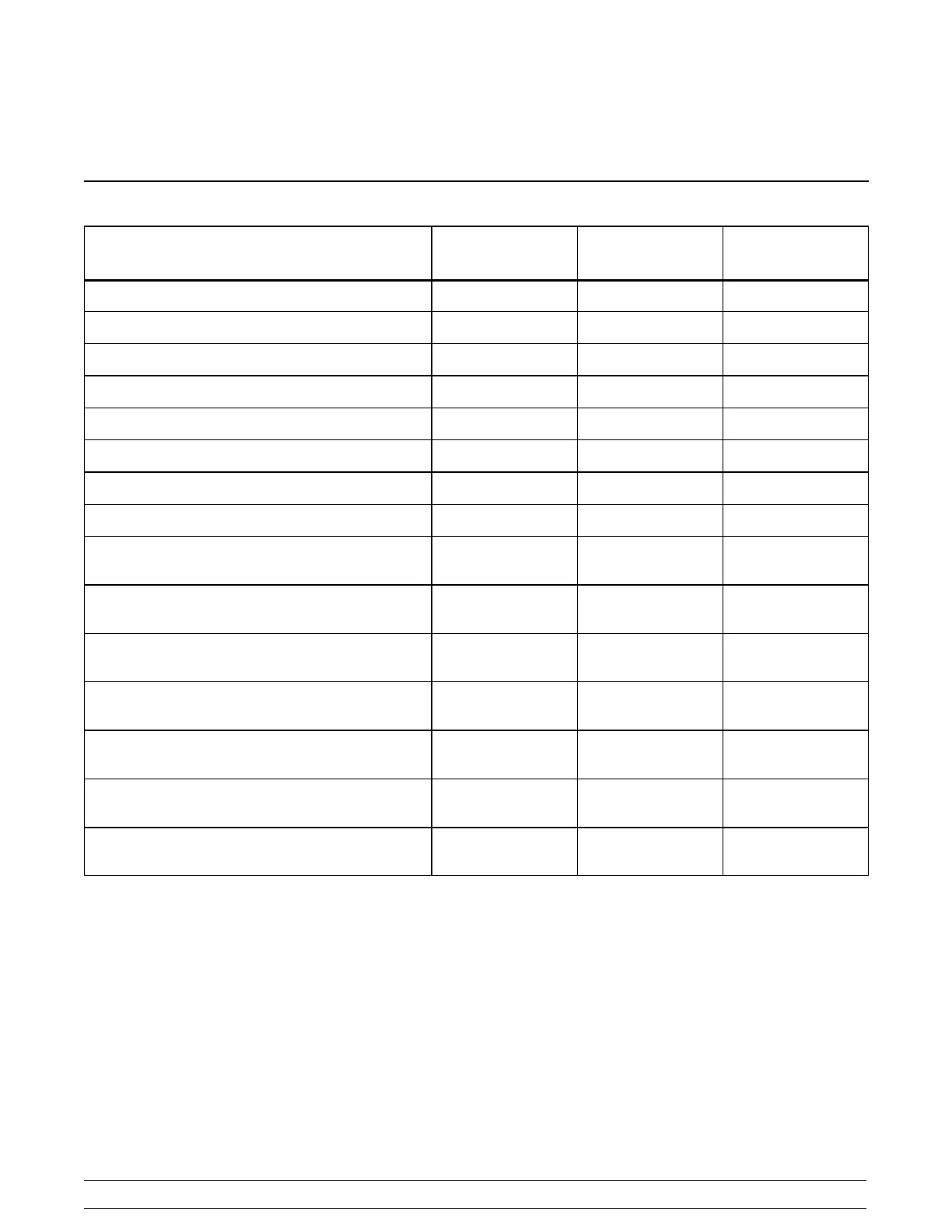
Section 9 Parts Replacement Schedule
PART DESCRIPTION EVERY
3MONTHS
EVERY
6MONTHS
ANNUALLY
Drive Shaft Seal X
Scraper Blade X
Freezer Door Gasket X
Front Bearing X
Draw Valve O- Ring X
Prime Plug O- Ring X
Feed T ube O- Ring X
Air Orifice O- Ring X
White Bristle Brush, 3” x 7” Inspect & Replace
if Necessary
Minimum
White Bristle Brush, 1” x 2” Inspect & Replace
if Necessary
Minimum
Black Bristle Brush, 1” x 2” Inspect & Replace
if Necessary
Minimum
Double- Ended Brush Inspect & Replace
if Necessary
Minimum
White Bristle Brush, 1/2” x 1/2” Inspect & Replace
if Necessary
Minimum
White Bristle Brush, 3/16” x 1” Inspect & Replace
if Necessary
Minimum
White Bristle Brush, 3” x 1/2” Inspect & Replace
if Necessary
Minimum