6
3.2 CONNECTORS AND TERMINALS
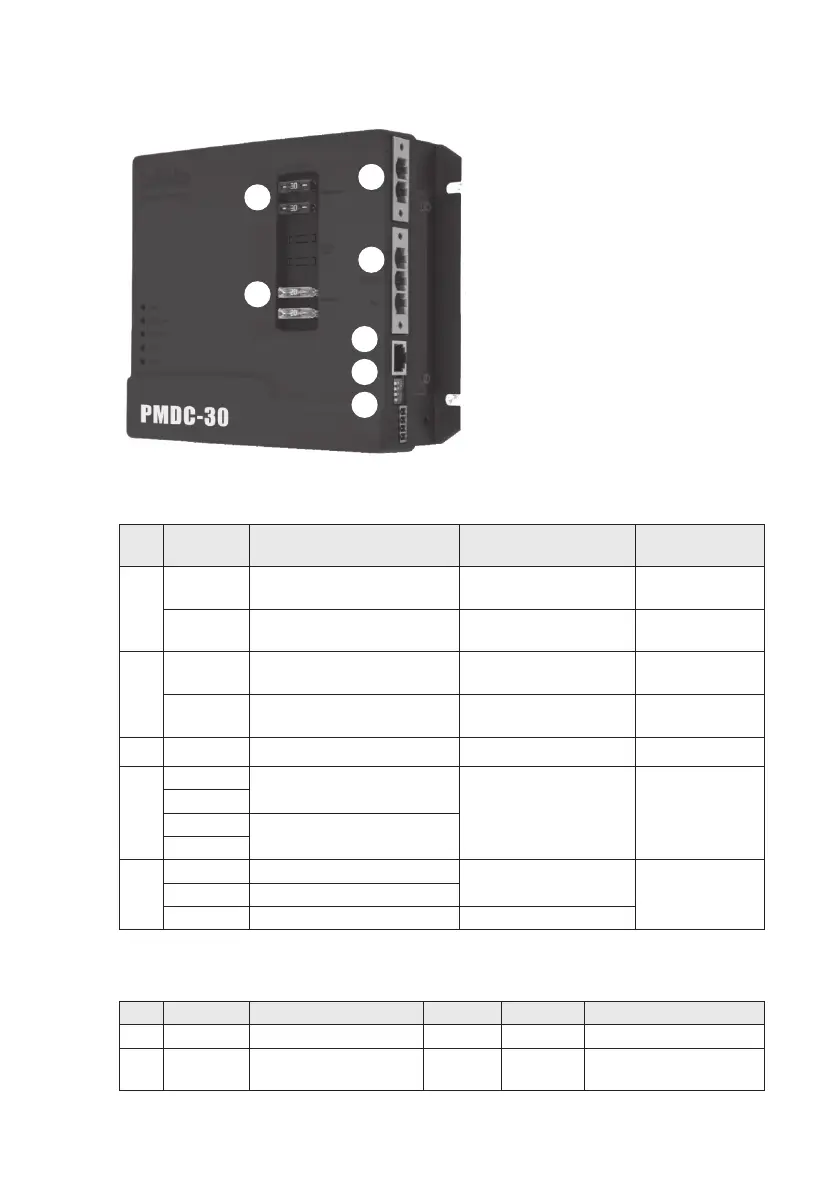
Figure 3-3: Connectors and terminals
Table 3-1: Connectors and terminals guide
No. Print PMDC-30 Remarks Circuit colours
and labelling
1
Alternator
Connects to positive of
Alternator
Or connects to positive
of motor battery
Red + Label
“Aux+”
BAT-
Connects to negative of
Alternator
Or connects to positive
of motor battery
Black – Label
“Aux-”
2
AUX BAT
Connects to positive of
auxiliary battery
Connect to IntelliJay
Red + Label
“Vehicle Batt+”
BAT-
Connects to negative and
negative of auxiliary battery
Connect to IntelliJay
Black – Label
“Vehicle Batt-”
3
COM For communication of RS485 Not Connected
4
1
Dip switch for output
current setting
Details of setting can be
found as Chapter 4.6
2
3
Dip switch for battery
type setting
4
5
BAT- Connects to BTS’ black cable
For battery temperature
sensing
RED Ring Terminal
connect to
Battery +ve
Temp Connects to BTS’ white cable
V-Sen Connects to BTS’ red cable For voltage sensing
Table 3-2: Fuse specification
No. Print Specification Colour Quantity Protection for
6 Alternator 30A/32VDC for PMDC-30 Amber 2 Input from alternator
7 AUX BAT 20A/32VDC Yellow 2
Output to charge auxiliary
battery
6
1
2
3
4
5
7