Do you have a question about the TCL TAC-09CHSA/XA31 INVERTER and is the answer not in the manual?
| Model | TAC-09CHSA/XA31 |
|---|---|
| Capacity (BTU) | 9000 |
| Energy Efficiency Ratio (EER) | 3.21 |
| Coefficient of Performance (COP) | 3.61 |
| Refrigerant | R32 |
| Power Supply | 220-240V, 50Hz |
| Outdoor Unit Weight | 26 kg |
| Type | Inverter |
| Cooling Capacity (kW) | 2.6 kW |
| Outdoor Unit Noise Level | 50 dB(A) |
| Operating Temperature (Cooling) | 18-43°C |
| Operating Temperature (Heating) | 24°C |
General disclaimer on service manual usage and manufacturer liability.
Required information for ordering replacement parts accurately.
Detailed measurements for the indoor unit.
Detailed measurements for the outdoor unit.
Explanation of all buttons and features on the remote controller.
Safety mechanisms and protections implemented by the controller.
How the 'Feel' mode adjusts settings based on room temperature.
Specifics of the cooling mode and compressor control.
A catalog of system failures and their corresponding error codes.
Codes indicating specific protection events or system states.
Detailed list of parts for the indoor unit with numbers and part names.
Detailed list of parts for the outdoor unit with numbers and part names.
Critical safety rules for installing the air conditioner.
Recommendations for safe operation and maintenance by the user.
Prohibited actions to prevent hazards and damage.
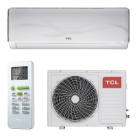
Visual guide to identifying parts of the indoor unit.
Visual guide to identifying parts of the outdoor unit.
General information on installation including pipe and cable specifications.
Steps and considerations for installing the indoor unit.
Steps and considerations for installing the outdoor unit.
Diagram illustrating the indoor and outdoor control system communication.
Labeling of key components on the Outdoor PCB.
Step-by-step guide to diagnose and fix E1 or E2 errors.
Step-by-step guide to diagnose and fix E6 error.
Procedure for diagnosing IPM or compressor malfunctions.
Tables showing resistance and voltage characteristics for temperature sensors.