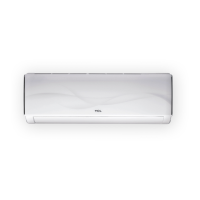
Do you have a question about the TCL TAC-09CHSD/XA31I and is the answer not in the manual?
| Brand | TCL |
|---|---|
| Model | TAC-09CHSD/XA31I |
| Category | Air Conditioner |
| Language | English |
Provides information on how to order spare parts, including required details like model number, part name, and quantity.
Details the dimensions and provides diagrams for the indoor unit.
Details the dimensions and provides diagrams for the outdoor unit.
Illustrates the refrigeration cycle diagram for cooling-only operation.
Illustrates the refrigeration cycle diagram for heat pump operation.
Explains the function of each button on the remote controller.
Describes how to set the remote controller type (Cooling Only vs. Heat Pump).
Details various safety protection mechanisms implemented in the electronic controller.
Explains the operation of the 'Feel' mode and its initial temperature settings.
Describes compressor frequency control and fan speed in cooling mode.
Details the system operation and settings for the DRY mode.
Explains frequency control, fan control, and cold air prevention in heating mode.
Details the conditions under which defrosting occurs and the process involved.
Describes the protection mechanism for indoor heat exchanger overheating.
Explains the operation and settings for the SLEEP mode.
Details how to use the emergency operation switch on the indoor unit.
Provides steps to activate the auto-restart function.
Describes how protection codes and failures are displayed on the unit.
Lists failure types, LED codes, and digital LED codes for troubleshooting.
Details protection types and their corresponding function indicators.
Explains LED indications for failures on the outdoor unit.
Lists failure types corresponding to blink times on the outdoor power board.
Provides the detailed wiring diagram for the indoor unit.
Provides the detailed wiring diagram for the outdoor unit.
Details the wiring diagram for the TAC-24CHSD/XA311 outdoor unit model.
Shows exploded view and lists parts for the TAC-09CHSD/XA311 indoor unit.
Shows exploded view and lists parts for the TAC-09CHSD/XA311 outdoor unit.
Shows exploded view and lists parts for the TAC-12CHSD/XA311 indoor unit.
Shows exploded view and lists parts for the TAC-12CHSD/XA311 outdoor unit.
Shows exploded view and lists parts for the TAC-18CHSD/XA311 indoor unit.
Shows exploded view and lists parts for the TAC-18CHSD/XA311 outdoor unit.
Shows exploded view and lists parts for the TAC-24CHSD/XA311 indoor unit.
Shows exploded view and lists parts for the TAC-24CHSD/XA311 outdoor unit.
Provides safety rules and recommendations specifically for the installation process.
Outlines safety rules and recommendations for the user during operation and maintenance.
Lists prohibitions and critical safety warnings to prevent hazards during appliance use.
Identifies and illustrates the key parts of the indoor unit.
Identifies and illustrates the key parts of the outdoor unit.
Covers connecting pipe lengths, refrigerant piping, and connecting cables.
Provides guidelines for the proper placement of indoor and outdoor units.
Step-by-step instructions for installing the unit's mounting plate.
Instructions for drilling the wall hole to accommodate the piping.
Procedure for making electrical connections to the indoor unit.
Details on how to connect the refrigerant piping correctly.
Steps for connecting refrigerant pipes to the indoor unit.
Guidance on setting up the indoor unit's condensed water drainage system.
Procedure for making electrical connections to the outdoor unit.
Instructions for connecting refrigerant pipes to the outdoor unit.
Steps for bleeding the refrigerant circuit using a vacuum pump.
Diagram illustrating the components and connections of the outdoor control system.
Overview of the structure and components on the Outdoor Unit PCB.
Provides detailed information on the connections to the Outdoor Unit PCB.
Illustrates the flow of current between the indoor and outdoor units.
Provides reasons and solutions for display errors E1 or E2.
Provides reasons and solutions for display error E6.
Provides reasons and solutions for display errors E3 or E7.
Provides reasons and solutions for display error E8.
Provides reasons and solutions for display errors E0 or E5.
Provides reasons and solutions for display error EA (Current Sensor Fault).
Provides reasons and solutions for display error E9 (Outdoor PCB Drive Damage).
Provides reasons and solutions for display error EU (Voltage Sensor Damage).
Provides reasons and solutions for display error EE (EEPROM Fault).
Explains the cause and solution for the CL display (Filter Duty).
Flowchart for diagnosing outdoor unit IPM or compressor malfunctions.
Flowchart for diagnosing and resolving DC Over Current errors.
Flowchart for diagnosing and resolving E0, E5 errors related to communication.
Provides temperature vs. resistance data for indoor and outdoor sensors.
Details temperature vs. resistance data for the outdoor unit's discharge pipe sensor.
Introduces R32 and R290 refrigerants and their properties.
Specifies the required room area for installing R32/R290 air conditioners.
Covers site safety, operation safety, and specific installation safety measures.
Details pre-maintenance checks for the environment, equipment, and unit.
Lists specialized tools required for air conditioner maintenance.
Procedure for inspecting the system for refrigerant leaks before maintenance.
General safety principles to follow during maintenance operations.
Guidelines for the proper location and setup of the maintenance station.
Steps and requirements for filling refrigerants into the system.
Safety precautions and procedures for welding during maintenance.
Guidelines for maintaining and servicing the unit's electrical components.
Steps to take for handling emergency situations, such as refrigerant leaks.





 Loading...