ZK300DC SWING GATE OPERATOR USER’S MANUAL
7
To release the operator by turning the release nut anticlockwise.
The gate is mounted on one face of the mounting post, and the operator is mounted on the
face 90 degrees from it. Below is schematic of push to open configurations.
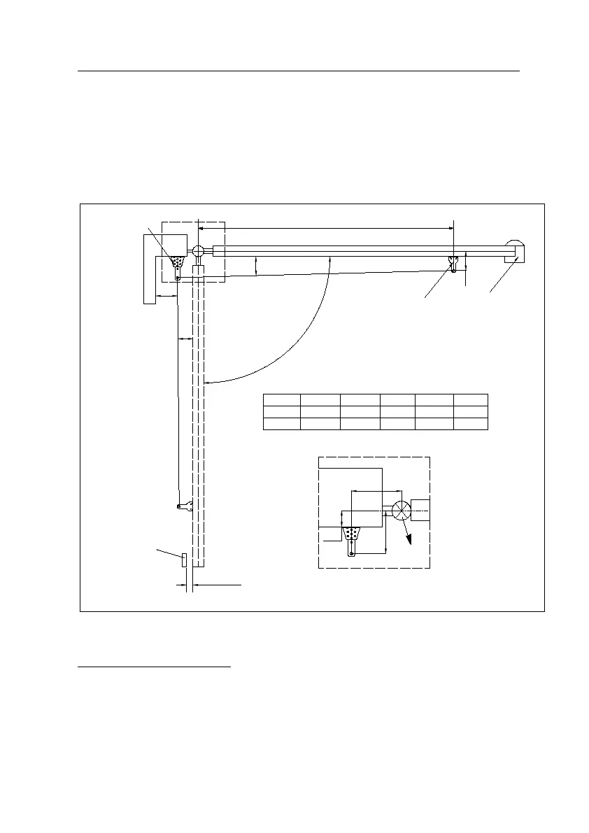
As shown in the diagram below, correctly mounting geometry assures that the desired
degrees of swing are achieved, that the gate speed is correct, and that the operator and
gate will operate properly and have a long life.
A
B
α
Hinge
Post
Post bracket
Gate bracket
105°
90°
50
50130
115150
135
αCmaxBA
Cmax
>0°
>0°
D
E
D E
110
110
975
974
5-10mm
Stop block
(Open position)
Base plate
(close position)
>100
Fig.4 Pull to open mounting geometry
Install automatic gate operator (see Fig.5)
Locate the gate operator between the two hinges, the installation height range is 300 –
800mm. this will prevent the gate from twisting and flexing. Add a cross bar on the gate if
necessary.
Note: If the operator is mounted at a height above the specified range, and the gate is not
sturdy enough, then it may result in bending or damage to the gate and gate operator.