Digital and Analog Logical Connections 7.2.5.3
Configurable logical inputs (see FIG. 18A)
All inputs are optically isolated from the internal regulation. L.I.C. is the
common of the inputs L.I.5, L.I.6, L.I.7, L.I.8.
24Vdc ±10% Imax=10mA
Common of all logical inputs to be connected to the negative of the input
power supply.
Fast configurable logical outputs (max. 5 kHz) (see FIG. 18C).
All outputs are optically isolated from the internal regulation.
The transistor is conductive when the output is ON.
Imax = 60 mA @ 30Vdc
Configurable logical outputs with relay contact.
The contact is normally open.
Imax = 1A @ 30VDC / 0.3A @ 125VAC
Configurable analog inputs (see FIG. 18B).
Inputs: +/-10V (max. 0.5 mA) or 4 ÷ 20 mA, settable with the appropriate
jumpers.
Configurable analog output (see FIG. 18D).
Output: ± 10V /2mA.
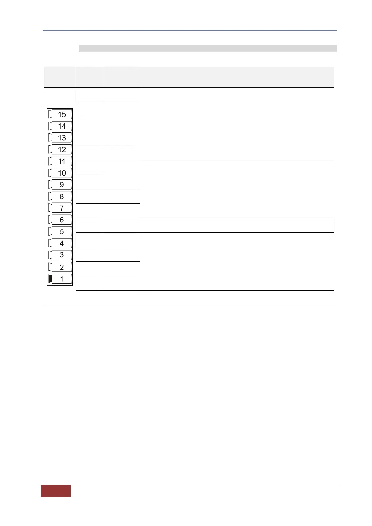
TAB. 17 – Connections: Digital and analog I/O