CONNECTION OF OPTIONAL CARDS 7.4
7.4.1 CAN BUS
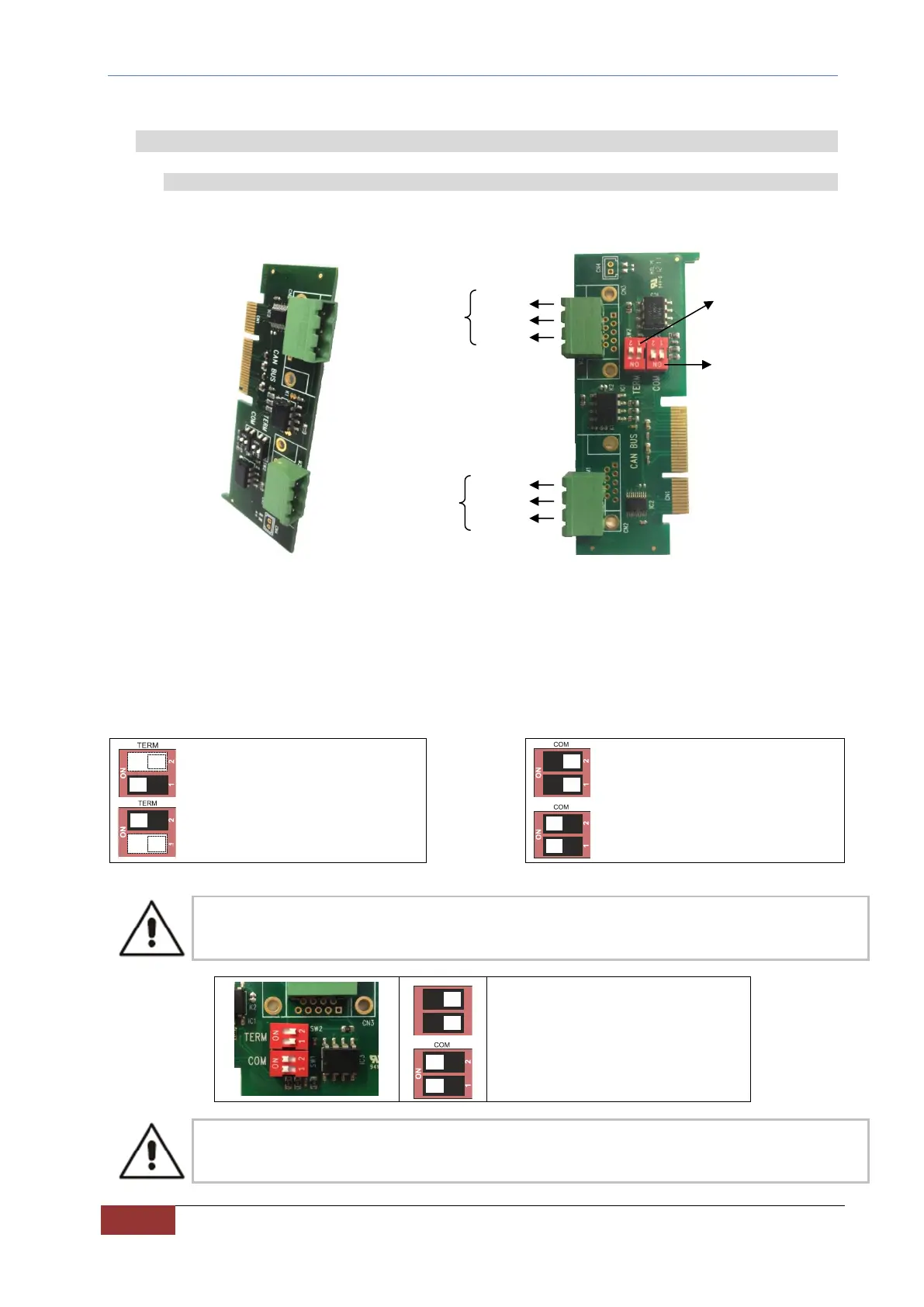
The pin assignment of the optional card for CAN BUS communication is given here below.
FIG. 21 – CAN bus card
On the card there are 2 double dip switches identified as:
- TERM
- COM
The contacts of the dip switch "TERM" (one for each CAN connector), if set to ON, enable the terminating resistor
(120 Ω) between CAN H and CAN L.
The contacts of the dip switch "COM" join the signals CAN L and CAN H of the two Buses so that the two connectors
can be used one as input and one as output. The two dip switches shall always be positioned in pairs.
BUS 1 not connected to BUS 2
BUS 1 connected to BUS 2
IF BUS 1 AND BUS 2 ARE CONNECTED TOGETHER, NEVER CONNECT BOTH THE TERMINATION
RESISTORS (TERM dip switches).
Default setting: BUS 1 and BUS 2
connected together, but not terminated.
ANY OPERATION MUST BE MADE ONLY WITH CONVERTER NOT POWERED.
CAN L
CAN L
 Loading...