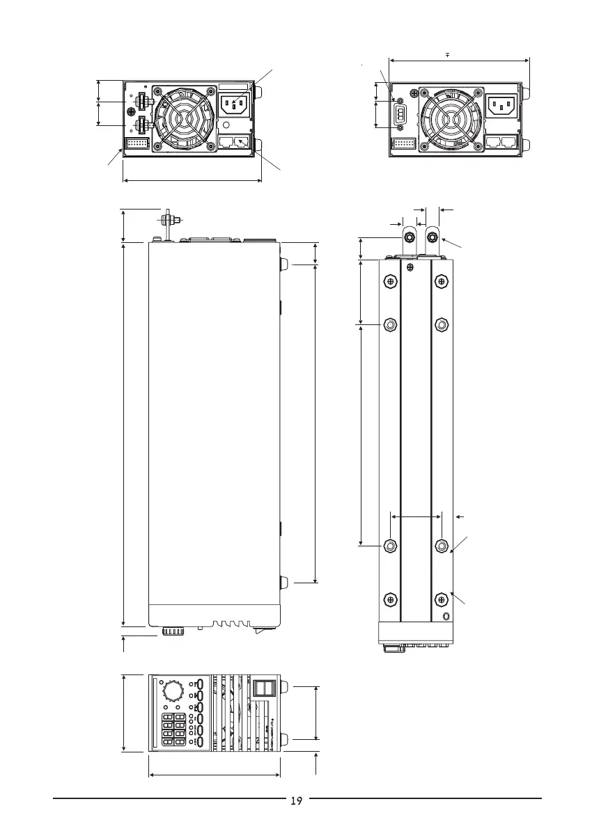
3.10 OUTLINE DRAWINGS
ZUP 200W and ZUP 400W Series
DIMENSIONS: mm
200W /400W units:
70x124x350
WEIGHT: Kg
200W units: 2.9
400W units: 3.2
20.0
20.0
13.0
13.0
59.5
30.0
(Note4)
70.0
201.5
11.0
+
0.5
_
+
+
0.5
0.5
_
_
350.0
+
1
_
290.0
+
1
_
+
1
_
124.0
48.0
11.0
Mounting Holes
Tap M4 x 4 marked ‘A’
(See note 1)
Notes:
1. Mounting screws must not
protrude more than 6mm
into the power supply.
2. Use M6 or 1/4” screw for
load wires connection,
enclosed in the package
at time of shipment.
3. Receptacle: AMP, 87631-9,
14 contacts, double row.
Pin: 87523-5 or 87523-6
4. For 6V to 60V models.
5. Male connector (P.S. side) :PSC 1.5/3-M-PE , Phoenix
Accessories: Female connector (user side) :PSC 1.5/3-F , Phoenix
Strain relief plastic housing.
Rubber Bumpers
4 places marked ‘B’
(removable)
10.6
B
B
B
B
A
A
A
A
48.4
_
+
0.5
21.5
19.0
External
Control
Connector
(Note3)
IEC320
AC Inlet
RS232/RS485
communication
connectors
+
1
_
131.0
A
ALM
CC
CV
V
POWER SUPPLY
ADDR
OVP/UVP
V/A
FOLD
REM
OUT
POWER
NEMIC-LAMBDA
LTD.
H
25.0
17.5
(Note 5)
(Note 2)
131.01.0
6V TO 60V MODELS
80V AND 120V MODELS