5.5.3 Output control continued
#
Commands
13 :UVPn;
Description
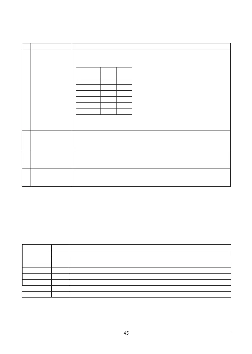
Sets the under-voltage protection limitsin volts. Under-voltage range
settings are given in table 5-4:
Model MIN.
MAX.
ZUP6-XY 0.00
5.98
ZUP10-XY 0.00
9.97
ZUP20-XY 00.0
19.9
14 :UVP?;
15 :ASTn;
16 :AST?;
Example-ZUP20-XY :UVP07.3;
example- UP07.3
Returns the string followed by the present programmed under-voltage
protection value. The under-voltage range is given in table 5-4.
UP
Sets the auto-restart mode to On or Off.
:AST1; -Auto-restart is On
:AST0; -Auto-restart is Off
Returns the string followed by the auto-restart mode status.
AS1 -Auto-restart is ON
AS0 -Auto-restart is Off
AS
Table 5-4: Under-voltage programming range.
ZUP36-XY 00.0
35.9
ZUP60-XY 00.0
59.8
ZUP80-XY 00.0
79.8
ZUP120-XY 000.0
119.8
1. Operational Status Register:
The operational status register records signals that are part of the power supply’s normal operation. In
addition to the normal operation data, the register holds an alarm bit which indicates that one of the
alarm (fault) register bitsis set. The register is automatically updated and reading it does not change it’s
content. Clearing the register is done by DCL command. See table 5-5 for Operational Status Register
content.
Note:
*1 In case ofAC fail, the alarm status register ‘AC fail’bit will be set but will not set the alarm bit.
5.5.4 Status control
5.5.4.1 Registers structure
Table 5-5: Operational status register content.
Bit Name
Bit No Meaning
cc/cv
1
‘0’ - Indicates constant voltage, ‘1’ - constant current.
‘1’ - Indicates auto-restart is on, ‘0’ - auto-restart is off.
‘0’ - Indicates foldback protection SRQ is disabled , ‘1’ - enabled.
‘0’ - Indicates over voltage protection SRQ is disabled , ‘1’ - enabled.
‘1’ - Indicates output is on , ‘0’ -output is off.
‘0’ - Indicates over temp. protection SRQ is disabled , ‘1’ - enabled.
‘1’ - Indicates foldback protection is armed.
fold
2
ast
3
out
4
srf
5
srv
srt
alarm
6
8
7
‘1’ - Indicates that an alarm register bit is set. (note*1)