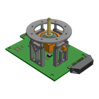
The TDK Joystick Evaluation Platform (HAL 3900) is a device designed to demonstrate the use of a Direct Angle Magnetic Sensor in a joystick configuration. While the HAL 3900 is the primary sensor used, the platform is adaptable to other TDK-Micronas product line sensors.
Function Description:
The core function of the platform is to evaluate the HAL 3900, a 3D position sensor based on Hall-effect technology. This sensor incorporates an array of horizontal and vertical Hall plates utilizing TDK-Micronas' 3D HAL technology. The Hall plate signals are processed through two/three separate A/D-converters, filtered, and temperature compensated. An optional linearization block can be employed to minimize overall system non-linearity errors that may arise from mechanical misalignment or magnet imperfections. Offset compensation, achieved through spinning current, reduces errors due to supply voltage and temperature variations, as well as external package stress. The device also features automatic stray-field compensation, compliant with ISO11452-8. Communication with the sensor is established via an SPI interface.
The Joystick Module supports three primary measurement configurations:
- 3D Position Detection: In this setup, the sensor is centrally located within the joystick module, detecting the position of a magnet housed inside the joystick lever.
- 3Z Rotational Measurement: Two sensors are positioned at the sides of the module, at X and Y coordinates. These sensors detect the rotation of 2-pole magnets fixed at the ends of the revolving joints. The sensors are placed on the "4 Pole 180 DEG" side of the Side PCBs, facing the magnet.
- XY Rotational Measurement: Similar to 3Z rotational measurement, two sensors are placed at the sides of the module (X and Y coordinates) to detect the rotation of 2-pole magnets at the ends of the revolving joints. In this configuration, the sensors are placed on the "2 Pole 360 DEG" side of the Side PCBs, facing the magnet.
The platform is delivered with two distinct joint types: Revolving Joint and Gimbal Joint. The functionality of a Universal Joint is covered by the Revolving Joint assembly. Users can assemble any of these joints, and the provided software supports all three configurations.
Important Technical Specifications:
- Sensor Type: HAL 3900 (3D Position Sensor based on Hall-effect technology).
- Hall Plate Technology: TDK-Micronas' 3D HAL technology.
- Signal Processing: Two/three separate A/D-converters, filtering, temperature compensation, optional linearization block, offset compensation via spinning current, automatic stray-field compensation (ISO11452-8).
- Communication Interface: SPI.
- Power Supply: The Joystick Module PCB features two unique power supply lines, VDD1 and VDD2, to ensure compatibility with biphase communication. Sensors 1 & 3 are powered by VDD1, and Sensors 2 & 4 are powered by VDD2. When using a TDK MSP or TDK SPI Programmer, the power supply is managed irrespective of the VDD line connection.
- Chip Select Lines: Supports six different chip select lines, allowing communication with up to six different sensors. This enables multiple PCBs to be connected in tandem with a compatible communication device.
- Arduino Power Bridge: By default, Arduino 5V and 3V pins are floating. To connect these pins to a power supply line (VDDx) for the Arduino, a 0603 0R resistor must be soldered on the Arduino power bridge between the desired voltage level and VDDx.
- Biphase Communication Support: The PCB is designed to support biphase communication, although the evaluation environment primarily uses SPI. Biphase communication can be established via an edge card connector or by soldering an RJ25 connector. A biphase bridge (J003) allows selection of which sensor (1 & 3 to OUT1, 2 & 4 to OUT2) is connected to the output. Each OUTx line supports only one sensor, limiting the maximum simultaneous use to two sensors.
Usage Features:
- Assembly Flexibility: The module comes with Revolving and Gimbal joint types, allowing users to assemble the preferred configuration. The software supports all three joint assemblies (Revolving, Gimbal, and Universal).
- Software Evaluation Environment: A LabVIEW™-based evaluation software, "Joystick/Shift-by-wire Evaluation Platform," is available for download (registration required). This software provides:
- Communication interface to the sensor.
- Visualization of Magnetic Field characteristics.
- Visualization of Joystick position in a 3D environment.
- Ability to program the sensor when it is set to factory defaults.
- The installation includes the executable software, STL files for the 3D environment, and EEPROM dump files for sensor programming.
- Communication Device Options: The platform supports three communication devices:
- TDK SPI Programmer V1.x (preferred, supports all measurement configurations, can handle 3D position and rotational configurations on the same module).
- TDK Magnetic Sensor Programmer V1.x (original, only for 3D Position Detection, can accommodate a biphase sensor via RJ25 or TDK micro edge card to Dsub-25 adapter board).
- Arduino (for 3D Position Detection, requires the sensor to be pre-programmed and calibrated).
- Pre-calibrated Sensor Programming: The sensor is delivered with factory default values. For proper operation, a programming sequence is required using saved EEPROM dump files from pre-calibrated joystick modules. This ensures immediate access to the evaluation environment without further programming.
- Calibration Tool: For enhanced accuracy, the sensor can be calibrated using the HAL 3900 Programming Environment with a TDK SPI Programmer or TDK-MSP. A two-point calibration process is described, involving positioning the joystick lever at specific points and recording angle outputs.
- Interactive 3D Visualization: The software includes an interactive 3D image of the joystick module, allowing users to visualize the assembly process and the joystick's position in X and Y degrees.
- Magnetic Field Visualization: The Magnetic Field Tab displays magnetic field components (CUST_COMP Registers in mT) and sensor output angles (OUT1 and OUT2) for both 3D position detection and angular measurements (180° or 360°).
Maintenance Features:
- Resistor Soldering for Arduino: To enable Arduino communication, both Arduino headers must be soldered. A 0603 0R resistor needs to be soldered at the Arduino PWR bridge, connecting S1/3 and/or S2/4 to the desired voltage pad.
- CS Bridge Soldering: For Revolving Joint 3D Position Detection, a 0R 0603 resistor should be soldered on the CS Bridge between S1 and CS0. For Revolving Joint Rotational Position Detection, 0R 0603 resistors are soldered on the CS Bridge between S3 and CS2, and between S4 and CS3. For Gimbal Joint, a 0R 0603 resistor is soldered on the CS Bridge between S2 and CS1.
- Sensor Installation/Removal: Instructions are provided for soldering the HAL 3900 onto the Joystick PCB and for installing/removing sensors on the side PCBs, emphasizing the importance of removing unused sensors and noting the different positions for "2-pole 360 DEG" and "4-pole 180 DEG" sides.
- Magnet Orientation: If the joystick movement is inverted relative to the visualization environment, the magnet attached to the joystick module can be reversed.
- Airgap Adjustment: For 3D Position Detection, a magnet is inserted into the rev. lever slot, and its level is adjusted to achieve a 10mm air gap, with an airgap indicator at the lever's edge (2mm per notch).
- Firmware/Software Updates: The evaluation software and associated files (STL, EEPROM dumps) can be downloaded from service.micronas.com, suggesting potential for updates and new configurations.
- Troubleshooting: The manual provides notes on potential issues, such as damage from connecting other devices when an Arduino is present, and guidance on sensor programming for proper operation.