TDK-Micronas GmbH Page 14 of 23
3.3 Gimbal Joint
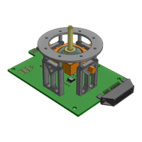
Figure 30: Gimbal Joint Complete
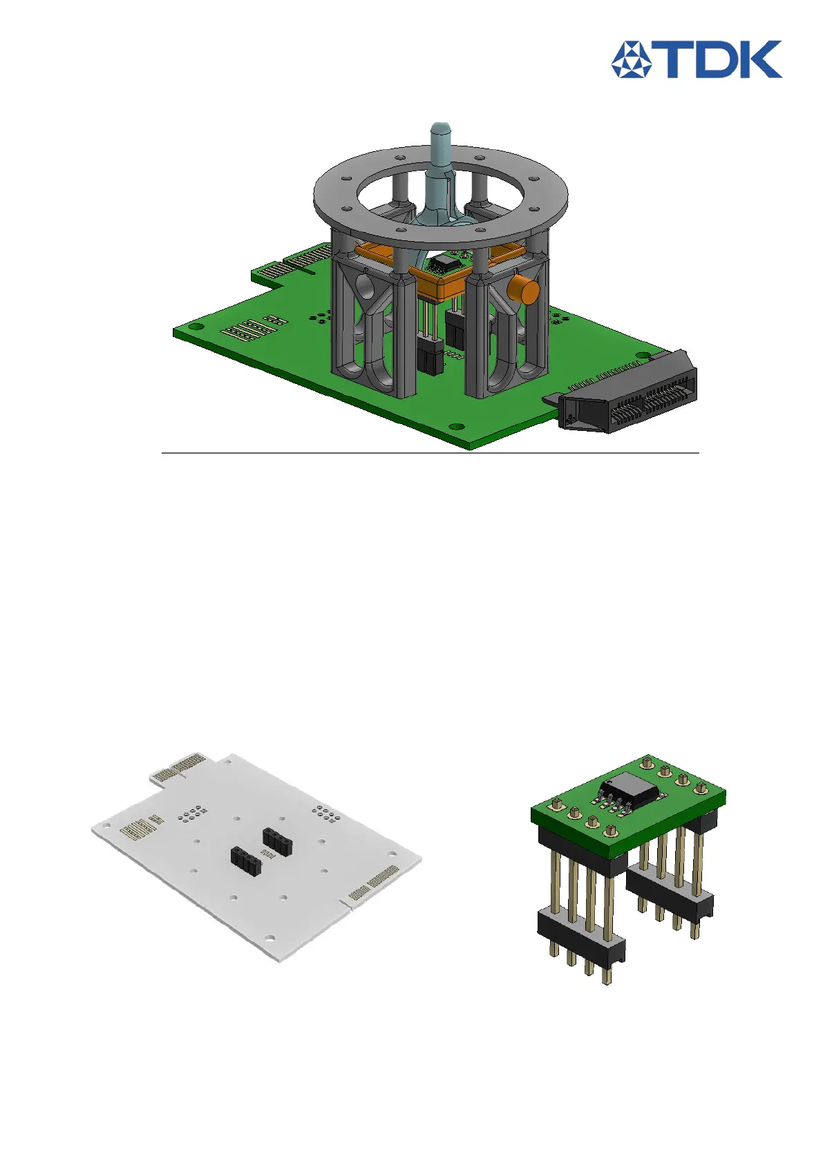
1. Solder the female header sockets at position S2
2. Solder the HAL3900 and raised headers on the raised PCB
3. Insert the raised PCB on the Joystick Module PCB at S2
4. Fix one holder on the joystick PCB using the provided brass screws.
5. Place the gimbal joint through the holder
6. Secure it with a second holder at the opposite side.
7. Screw the remaining holders
8. Insert a magnet in the slot of the gimbal stick until it is level with the bottom surface of the slot.
9. Push the gimbal lever onto the joint until it locks.
10. Place the top plane.
11. Solder a 0R 0603 on CS Bridge between S2 and CS1.
Figure 31: Gimbal Step 1 Figure 32: Gimbal Step 2 - Raised PCB assembly
1
2
1
2
3