TDK-Micronas GmbH Page 11 of 23
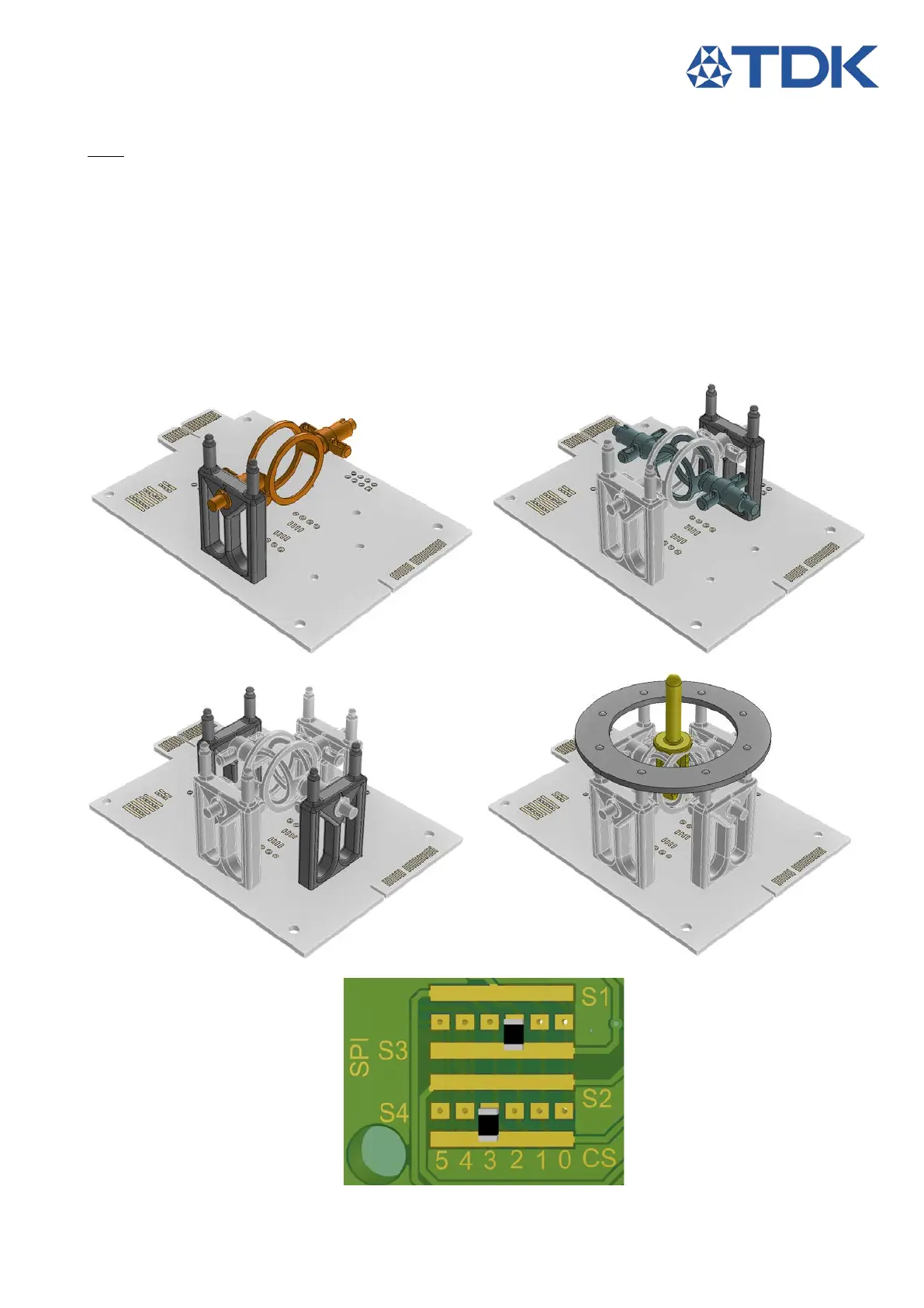
3.2.2 Rotational Position Detection
Note: The rotation of the joints is important, the two pole magnet ring fit only on one of the sides of each
joint
1. Fix one holder on the joystick PCB using the provided brass screws.
2. Place the large rev. joint through the holder
3. Secure it with a second holder at the opposite side.
4. Insert the small rev. joint through the large rev. joint and repeat steps 2 & 3.
5. Place the top plane.
6. Center both rev. joints and push the rev. lever trough the center slot until it locks.
7. Solder a 0R 0603 on CS Bridge between S3 and CS2
8. Solder a 0R 0603 resistor on CS Bridge between S4 and CS3
Figure 17: Revolving Rotational step 1 Figure 18: Revolving Rotational step 2
Figure 19: Revolving Rotational step 4 Figure 20: Revolving Rotational step 4
Figure 21: Revolving Rotational step 5
2
4
5
6
7