TDK-Micronas GmbH Page 12 of 23
Note: 1. Do not solder a sensor at the face of the side PCB that is unused, if a sensor is already present,
remove it.
2. The Position of the HAL 3900 on the "2-pole 360 DEG" side of the side PCB is lower than the
"4-pole 180 DEG" side.
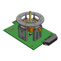
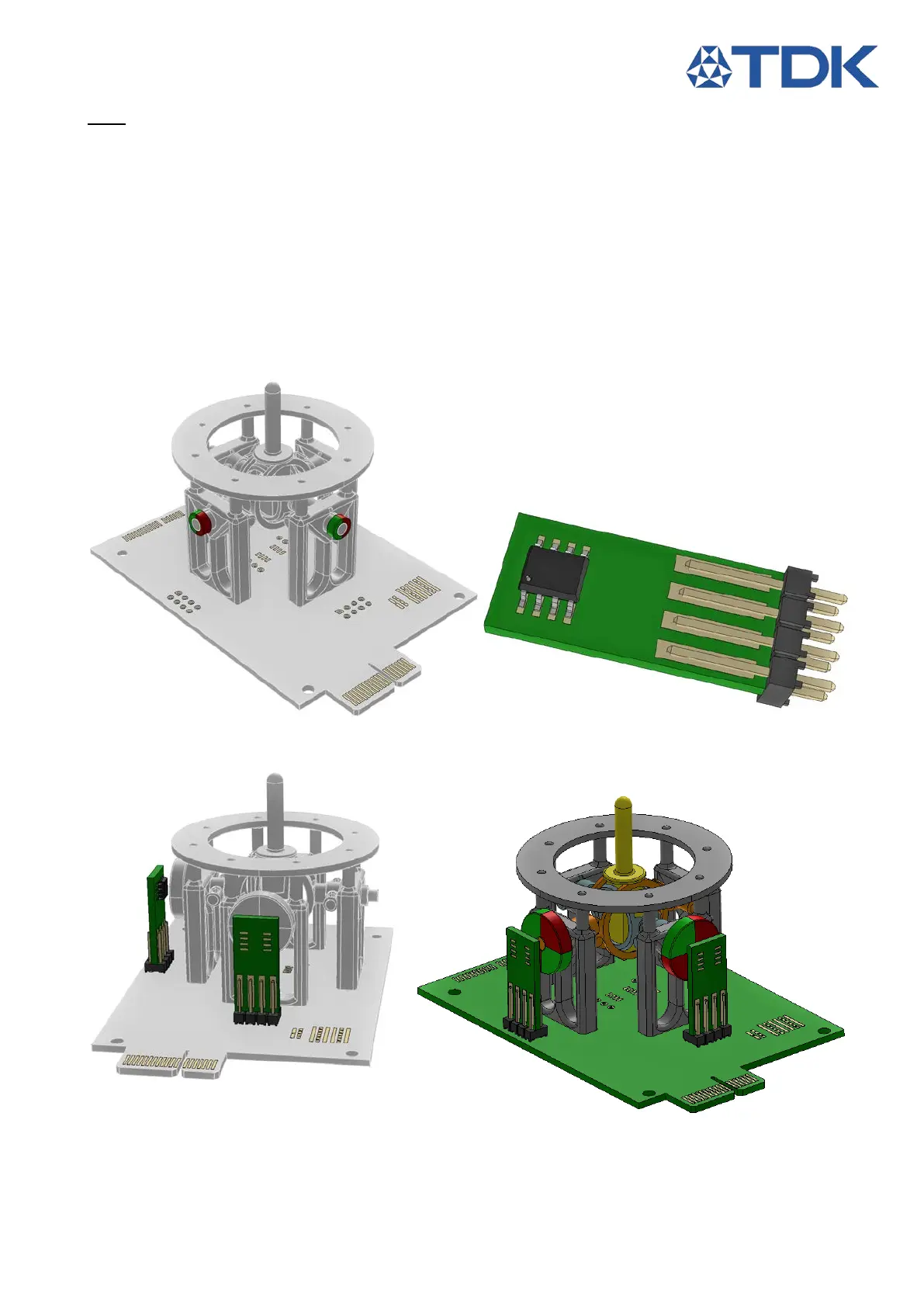
3.2.2.1 3Z rotational measurement
1. Fix the two 2-pole magnets at the sides of the joint (close to S3 and S4 connectors).
2. Solder the 2x4 Header at the edge of the two side PCBs
3. Solder the HAL 3900s on the two side PCB’s at the face indicating "4-pole 180 DEG".
4. Solder the Side PCBs to the Joystick PCB at S3 and S4 with the sensor facing the Joystick
module.
Figure 22: 2 pole magnets Figure 23: 3Z side PCB assembly ("4-pole 180 DEG" face)
Figure 24: 3Z side PCB installation Figure 25: 3Z complete
11 12
13
14
15