TDK-Micronas GmbH Page 8 of 23
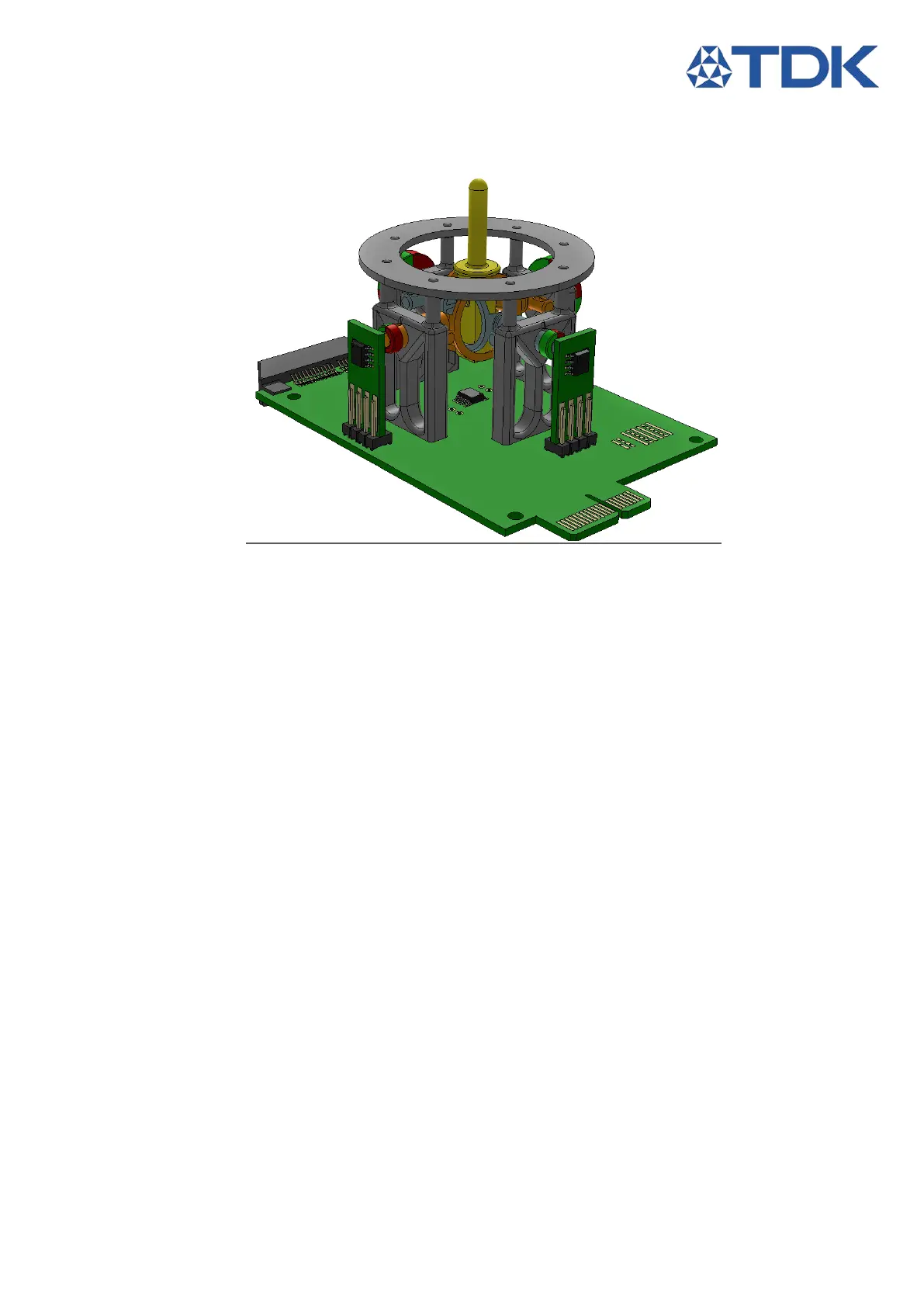
3.2 Revolving Joint
This setup can be used with three different measurement configurations of the sensor.
Figure 8: Revolving Joint complete
3.2.1 3D Position Detection
1. Solder the HAL 3900 on the Joystick PCB at S1
2. Fix one holder on the joystick PCB using the provided brass screws.
3. Place the large rev. joint through the holder
4. Secure it with a second holder at the opposite side.
5. Insert the small rev. joint through the large rev. joint
6. Use Brass Screws to fix the 3rd holder on the joystick PCB
7. Use Brass Screws to fix the 4rd holder on the joystick PCB
8. Insert a magnet in the slot of the rev. lever, make the magnet level with the bottom surface of the
lever for an air gap of 10mm, adjust the airgap as needed. Airgap indicator at the edge of the lever,
2mm per notch.
9. Place the top plane.
10. Center both rev. joints and push the rev. lever trough the center slot until it locks.
11. Solder a 0R 0603 on CS Bridge between S1 and CS0.