TDK-Micronas GmbH Page 21 of 23
5 Appendices
5.1 Appendix 1: Soldering Bridges
5.1.1 Chip Select
The Joystick module PCB supports six different chip select lines which translates to six different sensors
can communicate through the Joystick PCBs. The increased number of chip selects allows for more than
one PCB’s to be connected in tandem with a compatible communication device. This idea is illustrated in
Figure 39.
Figure 39: MSP(I) connected to two joystick modules
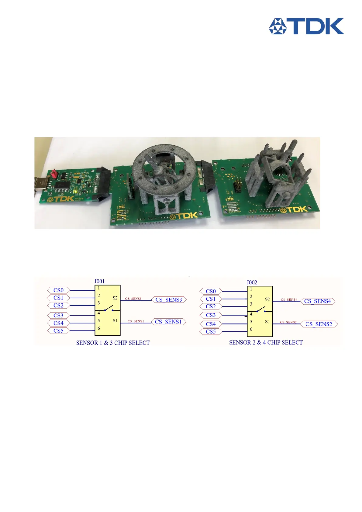
To achive that, the Joystick Module PCB is equipped with soldering bridges as shown on the schematic in
Figure 40. CS_SENSx stands for the chip select signal attached to the sensor. A 0603 0R resistor can be
soldered between the CS_SENS of any sensor to any chip select CS .
Figure 40: Chip select Bridges
5.1.2 Arduino Power Select
The Joystick Module PCB has two unique power supply lines VDD1 and VDD2 the reason behind this
design is the compatibility with biphase communication. As a result Sensors 1 & 3 are powered by VDD1
and Sensors 2 & 4 are powered by VDD2. When a TDK MSP or TDK SPI Programmer is used the power
supply