Page 15 MICROgarde controller I and II 04.20.11.18
Power Supply Connection
MICROgarde units without integral PSU
If you have purchased a MICROgarde unit without an integral power supply, you need to
connect the unit to a suitable PSU. This should be capable of supplying enough power for
the controller and its readers. In most cases, a 1A power supply is adequate. However, if
your installation consists of 4 Optica readers/keypads and a TCP/IP module, you should use
a 1.5A supply.
1. Connect the PSU to the MICROgarde’s 0V and 12V terminals using braid-screened
cable. Position the PSU as close as possible to the unit.
2. To minimize electrical interference, ensure that the MICROgarde and PSU are
grounded together: fasten the braid screen to both the main earth point in the PSU
and to the chassis plate of the MICROgarde.
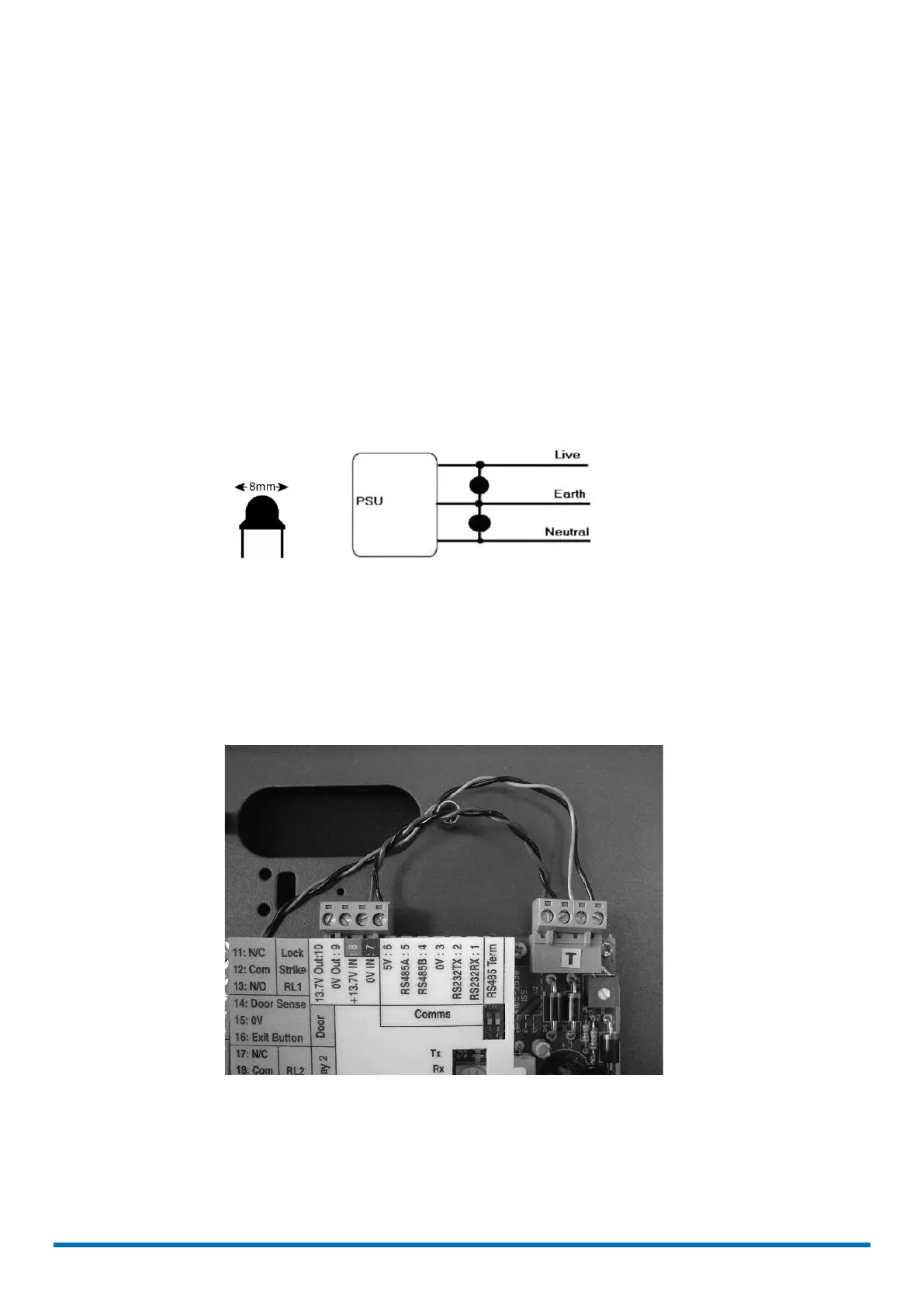
3. Fit two suppressors across the mains input to the power supply. Suitable suppressors
are provided with each MICROgarde non PSU unit. These are 470 pF (pico-Farad)
Class Y disc ceramic capacitors rated at 240V AC.
(a) Appearance and dimensions of PSU suppressor and
(b) connection to PSU
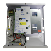
MICROgarde units with integral PSU
A MICROgarde controller with integral PSU features a high-quality 3A power supply.
The lock power MUST be taken from one of the 1A fuses supplied on the fuse board and not
from the power terminals (7, 8, 9 and 10) on the MICROgarde controller. Failure to do so
may result in unreliable operation of the door controller.
 Loading...