Page 22 MICROgarde controller I and II 04.20.11.18
Installing an Input/Output Module
You can add an I/O module to the PSU and non-PSU versions of the MICROgarde.
MICROgarde PSU version: the input/output module comes with 3 self-tapping screws
and 3 spacers for the metal cased MICROgarde. Fit these 3 screws through the I/O
board and then screw on the plastic spacers provided, before fitting and screwing to the
chassis.
MICROgarde non PSU version: the I/O module has a white plastic cover but a metal
chassis that has metal spacers already welded in position for the I/O board. Use the 3 x
standard M3 screws that are provided.
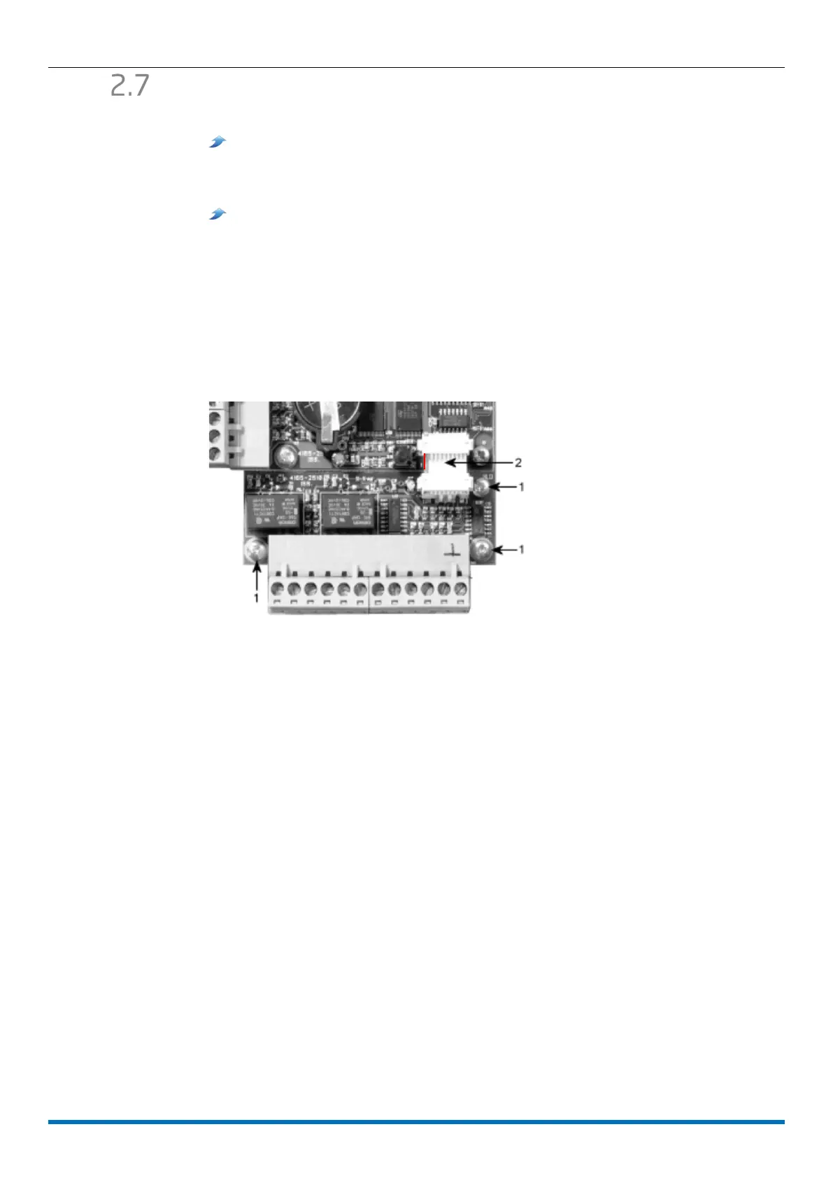
To fit the module:
1. Remove the connection label from controller.
2. Fit the I/O Module using 3 screws (labelled "1" in the picture).
3. Fit the ribbon cable (labelled "2" in picture).
The red wire of the ribbon cable should be adjacent to the tamper switch SW1.
4. Re-fit the connection label.
Installing an I/O module
Install the I/O before auto detecting the MICROgarde controller (see page Error! Bookmark
not defined.). The software then auto detects the I/O module.
 Loading...