04. 20.11.18 MICROgarde controller I and II Page 23
Installing a TCP/IP Module
The MICROgarde TCP/IP module can be connected to 100Mb or 10Mb networks. In order to
fully satisfy EU requirements for EMC and RFI, we recommend that this product only be
connected to a 10Mb network port. On a 100Mb network, we recommend connection via a
hub that is limited to 10Mb.
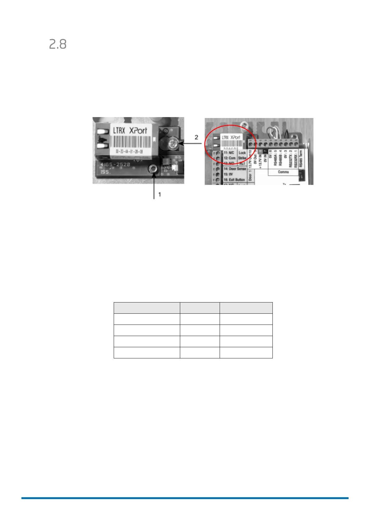
The IP module connects to the top edge of main board (see below).
Installing a TCP/IP module to a MICROgarde without PSU
5. Remove the connection label from the controller, remove the Comms 6 pin connector
(1-6), and temporarily remove power 4 pin connector (7-10). Remove 4 screws
securing the controller to the metal plate and lift the controller away from the metal
plate
6. Position the TCP/IP module over the pillar (labelled "1" in figure 2)
7. Fit the module to the plate with the screw provided (labelled "2" in figure 2)
8. Re-attach the main board to the metal plate and re-fit connection label
9. Connect the TCP/IP module to controller using the pre-wired connector provided.
TCP/IP connector
Colour Pin Label
Red 6 +5V
White 5 RS485A
Yellow 4 RS485B
Black 3 0V
10. Set the RS485 termination switches to the upper position; i.e. ON, at this
MICROgarde controller only: any other controller must have the RS485 termination
switches set to OFF).
 Loading...