Do you have a question about the TDSi MICROgarde I and is the answer not in the manual?
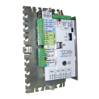
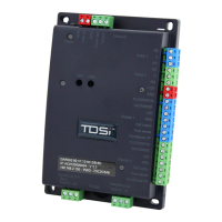
Details the physical components, connections, and internal workings of the MICROgarde controller unit.
Explains the process of card presentation, controller verification, and relay activation for door unlocking.
Provides guidance on mounting the MICROgarde controller chassis to flat surfaces and relevant environmental conditions.
Specifies the necessity of using screened cables for all connections to ensure reliability and EMC protection.
Explains the importance of grounding the controller chassis and cable screens to prevent interference and ensure system stability.
Explains the importance of grounding the controller chassis and cable screens to prevent interference and ensure system stability.
Details the connection procedures for various types of readers using different communication protocols.
Guides on connecting locks, power supplies, and the proper installation of suppressors for protection.
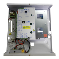
Provides instructions for connecting power supplies to MICROgarde units with and without integrated PSUs.
Checks the rotary switch setting, power-up status, and initial LED indicators after installation.
Tests card presentation to verify reader LED changes and confirm system readiness.
Guides through entering installer mode and testing relay activation for lock release.
| Model | MICROgarde I |
|---|---|
| Category | Controller |
| Manufacturer | TDSi |
| Power Supply | 12V DC |
| Max Readers | 2 |
| Max Doors | 1 |
| User Capacity | 2, 000 |
| Housing | Plastic |
| Communication | RS232, RS485 |
| Weight | 0.2kg |