Page 24 MICROgarde controller I and II 04.20.11.18
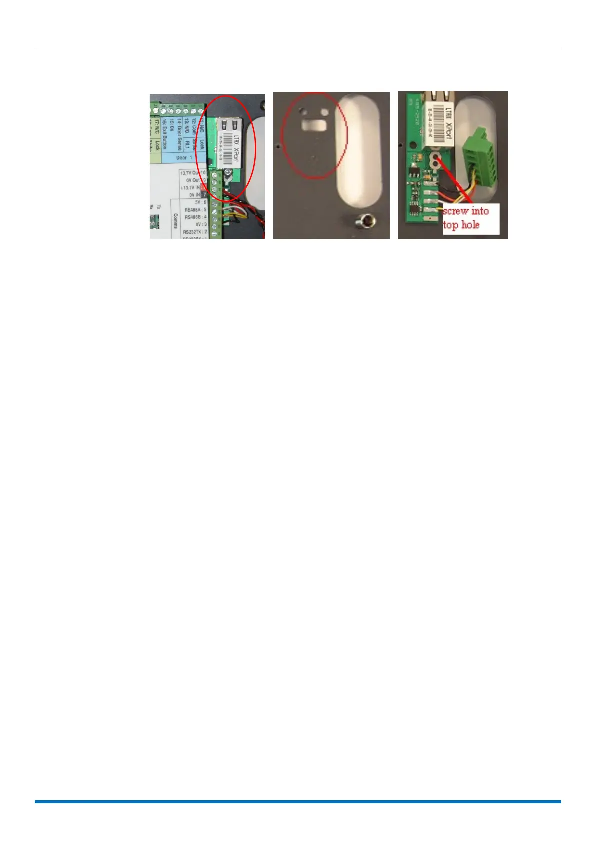
The IP module connects to the right edge of the main board (see Figure 18a).
Installing a TCP/IP module to a MICROgarde with PSU
11. Remove the green COMMS 6 pin connector (1-6), and temporarily remove power 4
pin connector (7-10).
12. At the back of the TCP/IP modules board, fit a black stud over each of the two holes in
the chassis (Figure 18b) situated on the right of the main board.
13. Position the module onto the chassis and secure with the self-tapping screw provided
into the upper of the 2 holes (see Figure 18c). The module sits securely and flat onto
the chassis.
14. Connect the TCP/IP module to the controller using the pre-wired connector provided
(see Table 5).
15. Reconnect the power 4 pin connector (7-10).
16. Set the RS485 termination switches to the upper position; i.e. ON, at this
MICROgarde controller only: any other controller must have the RS485 termination
switches set to OFF).
 Loading...