33
Section IV – Pipeline Under Pressure
2.0 Continued
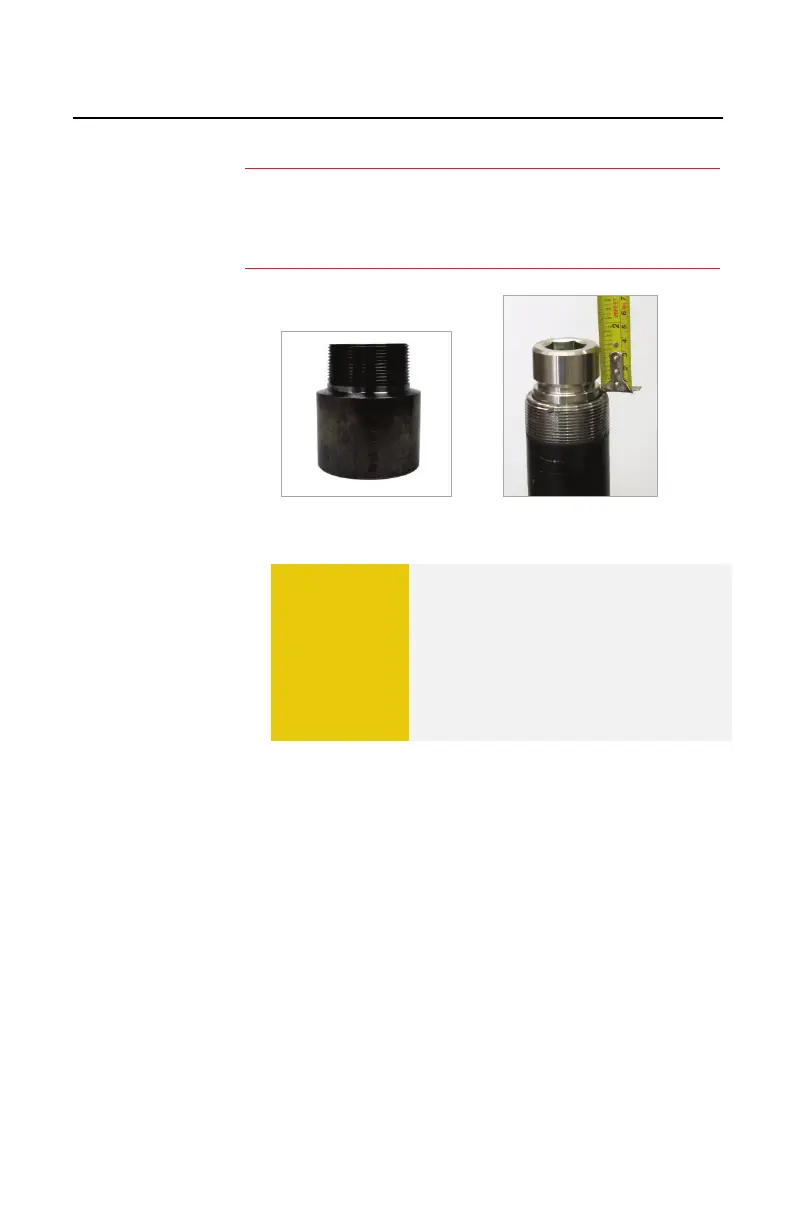
Figure 4.21. Optional Adapter
Figure 4.22. Installed Plug
F. Add dimensions “G”+”J”+”K” to give you the total
set dimension. The sum of measurements
“G”+”J”+”K” should be the body tube of the T-
101b reading when the PIG-SIG V is completely
set. Measure from the bottom of the feed tube
and mark this measurement on the body tube
(Figure 4.23). See EXAMPLE on following page.
:
An optional spacer may be installed to provide clearance to
reduce the risk of valve contact with the plug body (Figures
4.21 and 4.22).
CAUTION
The combination of Measurements
“G”, “J,” and “K” must not exceed 18-
inches, the maximum travel distance
of the T-101b Drilling Machine, or 28-
inches if using the T-101XL. If the
setting distance exceeds these
measurements, please consult the
factory for alternatives.
 Loading...