27
Section IV – Pipeline Under Pressure
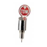
2.0 Indicator
Installation
2.0 INDICATOR INSTALLATION
2.1 Initial Test
A. Before installation, assemble the flag indicator
assembly cap onto the plug assembly. Push the
cap downward until fully seated.
B. Install the three set screws and tighten to 1.5 ft.-
lb.
C. Set the flag and operate the trigger a couple of
times to ensure the unit functions correctly
(Figure 4.3).
Figure 4.3. Verify
PIG-SIG V
Operation
D. After the test, remove the set screws and pull the
cap off the plug assembly.
NOTE:
Installation of the plug is the same for all PIG-SIG V types.
When installing an indicator assembly already installed in
a line, begin with Section IV, paragraph 2.3.
The cap will travel approximately 1-7/16 inches after
contacting the plug body.
CAUTION
Ensure hands and fingers are clear
of potential pinch points around the
flag when tripping or resetting the
 Loading...