53
Section V – Indicator Installation
1.0 Indicator
Installation
1.0 INDICATOR INSTALLATION
1.1 Installing the Indicator
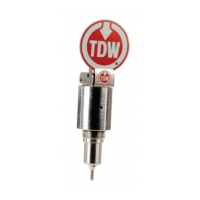
A. Locate the three set screws used in the flag
indicator body (Figure 5.1).
B. Apply a bead of silicone grease lubricant aroun
d
t
he housing O-ring (Figure 5.2).
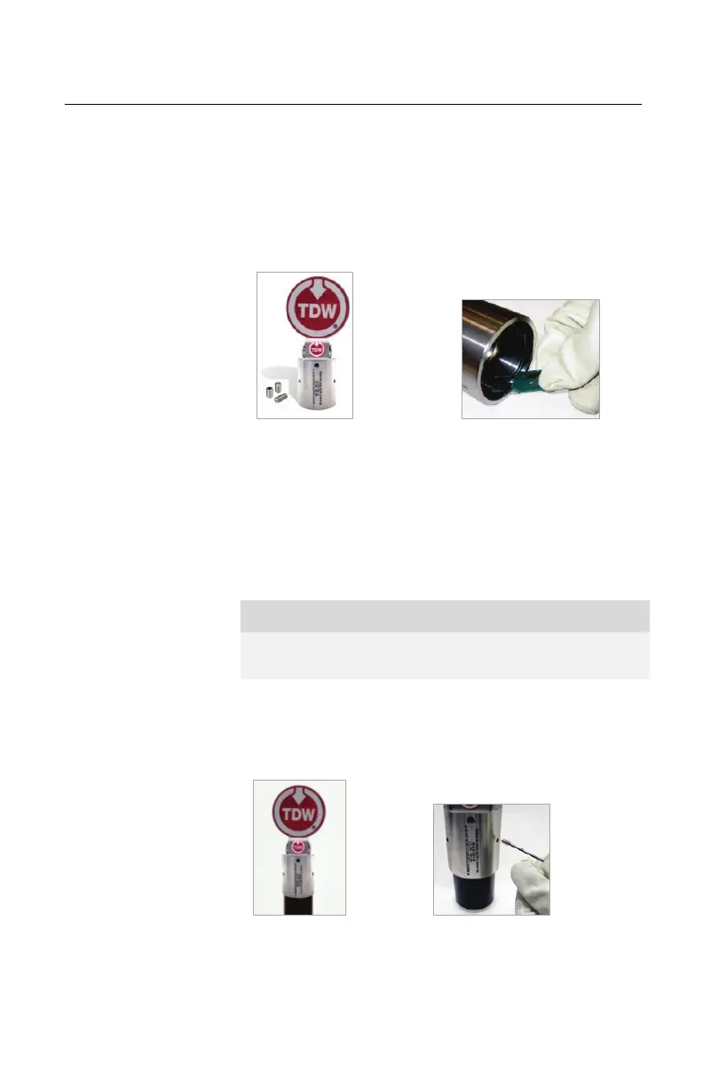
C. Place the indicator over the top of the plug an
d
pus
h down until it is fully-seated. The indicator
cap will completely cover the external threads
on
t
he nipple. Check set screw holes to see set
screw groove. Turn the indicator to desired fl
ag
or
ientation (Figure 5.3). Add glycol to plug cavity.
D. Install the three nylon-tipped set screws to secur
e
t
he flag indicator in place. Tighten to 1.5 ft.-lb.
(Figure 5.4).
Figure 5.4. Install Set Screws
Figure 5.2. Apply Lubricant
The cap will travel approximately 1-7/16 inches after
contacting the plug body.
 Loading...