42
Section IV – Pipeline Under Pressure
3.0 Plug
Recovery
3.0 PLUG RECOVERY
3.1 Preparations
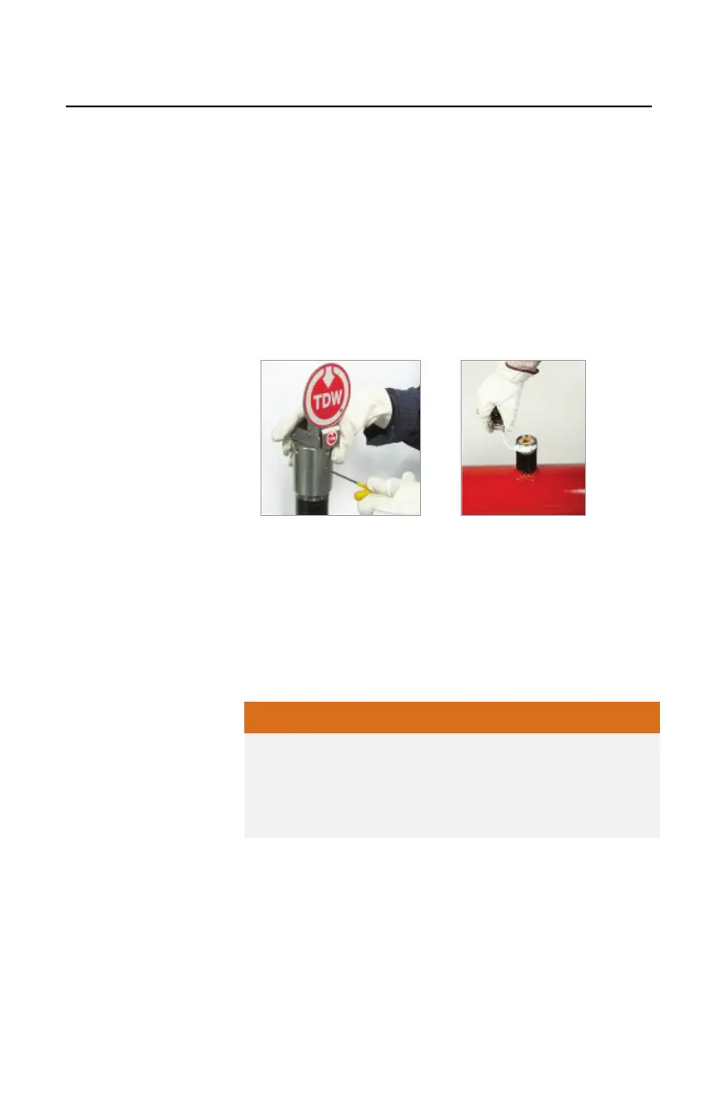
A. Remove the three set screws (Figure 4.40)
and
r
emove the flag indicator from the plug by pullin
g
s
traight up. Do not turn the cap during t
he
r
emoval process.
B. Clean the external threads and check for any
damage.
C. Threaded Valves: Apply thread paste (pi
pe
dope)
to the external threads (Figure 4.41).
Figure 4.40. Remove Set Screws.
Figure 4.41. Apply Thread
Paste
D. Select the appropriate tapping valve, whether
flanged or threaded, and install the tapping valve
onto the THREAD-O-RING fitting. Ensure the
valve has a minimum bore clearance of 2-1/16-
inches.
E. Lea
ve the valve in the open position.
Select a tapping valve which will allow the PIG-SIG to
pass through the bore. The bore should be
unobstructed by seat rings, lugs, etc. The bore of the
valve must be round and have a minimum inside
diameter of 2-1/16-inches.
 Loading...