35
Section IV – Pipeline Under Pressure
2.0 Continued
2.5 Aligning the Plug
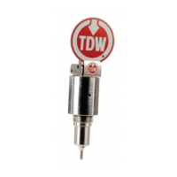
A. Install the bleeder valve (Figure 4.24) into the
3/8 x ¼-inch bushing on the base of the T-
101
D
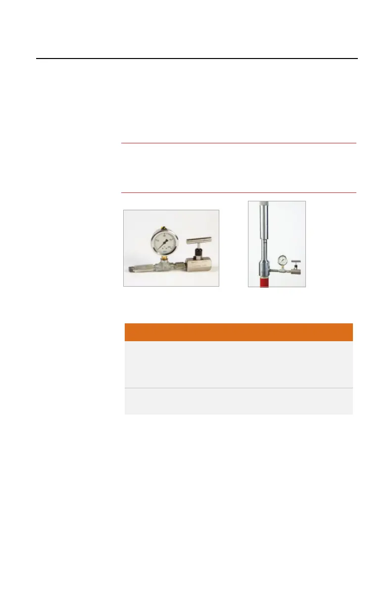
M (Figure 4.25). Leave the bleeder valve in t
he
open
position.
Figure 4.24. Bleeder Valve.
Figure 4.25.Installed Bleeder Valve
Vent pressure bleeder valve away from work area and
personnel. Stand clear of the vent when the bleeder
valve is opened. Otherwise, personal injury may result
Consider the dangers of product when purging from
the drilling machine adapter.
B. Open the tapping valve slightly to purge air
through the bleeder valve on the drilling machine.
When air is completely purged, close the bleeder
valve. Check the adapter connections for leaks.
C. Open the tapping valve to fully open position.
D. Rotate the feed tube clockwise, and extend the
boring bar until the bottom of the feed tube is two
inches from the mark on the body tube.
:
Depending on the product, the bleeder valve may be left in
the closed position. Refer to the appropriate Commodities
Procedure.
 Loading...