40
Section IV – Pipeline Under Pressure
2.0 Installation
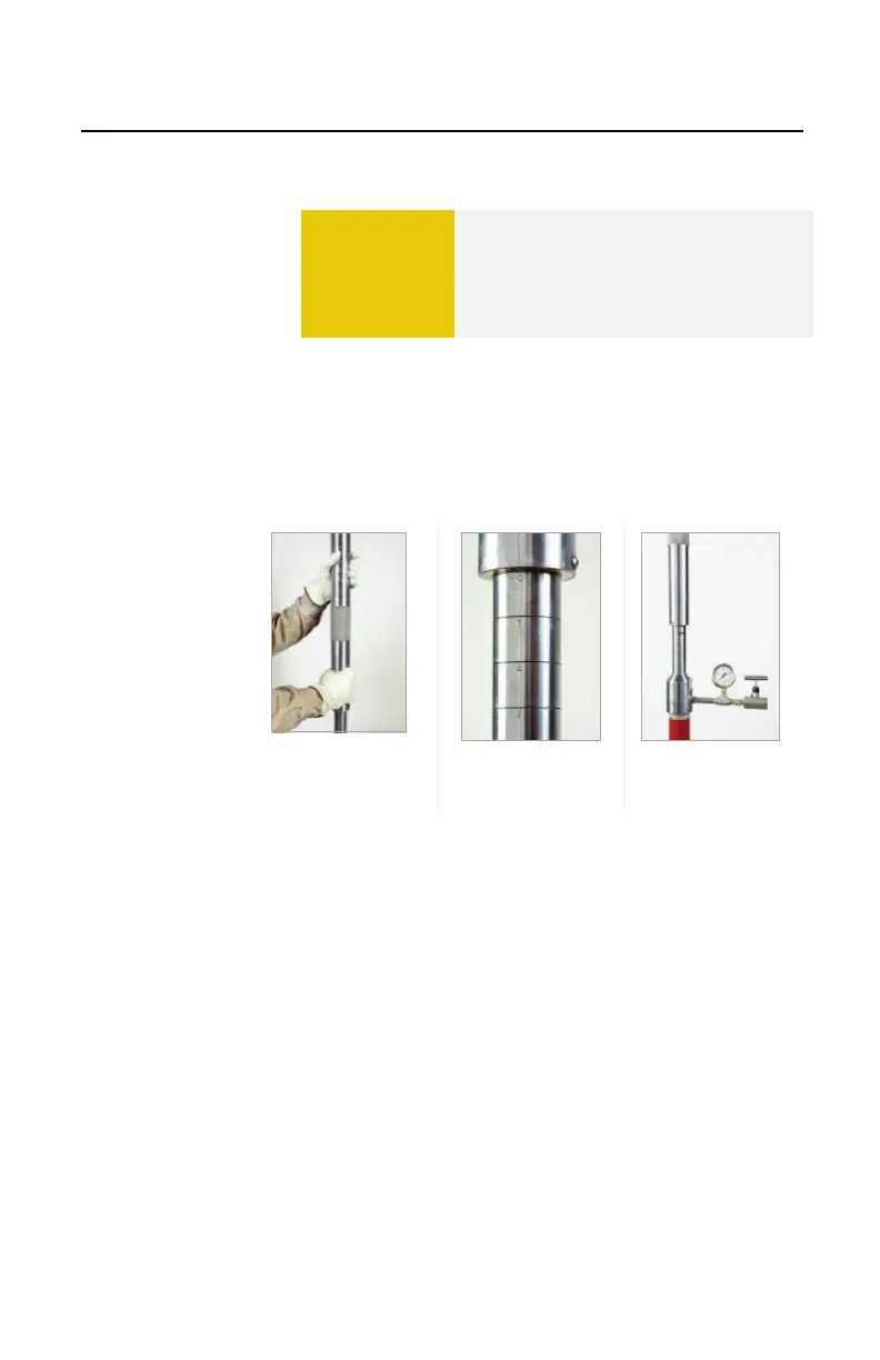
2.7 Removing the Drilling Machine
A. Once the pressure has been relieved and the
seal of the plug has been confirmed, rotate the
feed tube counterclockwise (Figure 4.33) to the
zero mark on the body tube (Figure 4.34).
B. Remove the bleeder valve from the 3/8 x ¼-inch
bushing (Figure 4.35).
Valve
C. If applicable, secure the drilling machine to lifting
equipment.
D. Unscrew the drilling machine from the tapping
valve (Figure 4.36).
E. Remove the tapping valve.
F. Install the PIG-SIG V indicator on the THREAD-
O-RING fitting. The top of the PIG-SIG V
assembly is designed to extend 1.38-inches
above the THREAD-O-RING fitting (Figure 4.37).
Figure 4.38 shows a completed Threaded Valve-
Mounted assembly. Figure 4.39 shows a
completed Valve-Mounted assembly.
CAUTION
Do not turn the crank handle
counterclockwise with the 1/8-inch
Allen socket head screw tightened or
the locking cap on the machine. This
will unthread the PIG-SIG V.
 Loading...