EasyManua.ls Logo

Teac FD-55 Series - 219

Teac FD-55 Series
73 pages
Print Icon
To Next Page IconTo Next Page
To Previous Page IconTo Previous Page
Loading...
explained
simple
model.
In
the
case
of
LI
<
L2,
shown
in
Fig.206,
the
allowable
cable
length
is
remarkably
shortened.
Enough
care
is
required
for
such
a
case.
For
the
system
design,
observe
the
input/output
signal
waveforms
both
at
host
and
FDD
sides
carefully
assuming
the
cable
connections
possible,
and
determine
the
maximum
cable
length
which
enables
the
interface
receivers
of
both
sides
to
receive
the
signals
correctly.
The
shorter
the
total
cable
length,
the
better
for
the
system
performance.
Therefore,
it
is
recommended
to
select
the
appropriate
length
of
cable
for
the
system
construction.
Though
the
length
is
different
depending
on
types
of
cable
and
types
of
host
side
receiver,
the
maximum
cable
length
in
a
typical
daisy
chain
connection
is
as
follows:
(Refer
to
item
2-2-3-1).
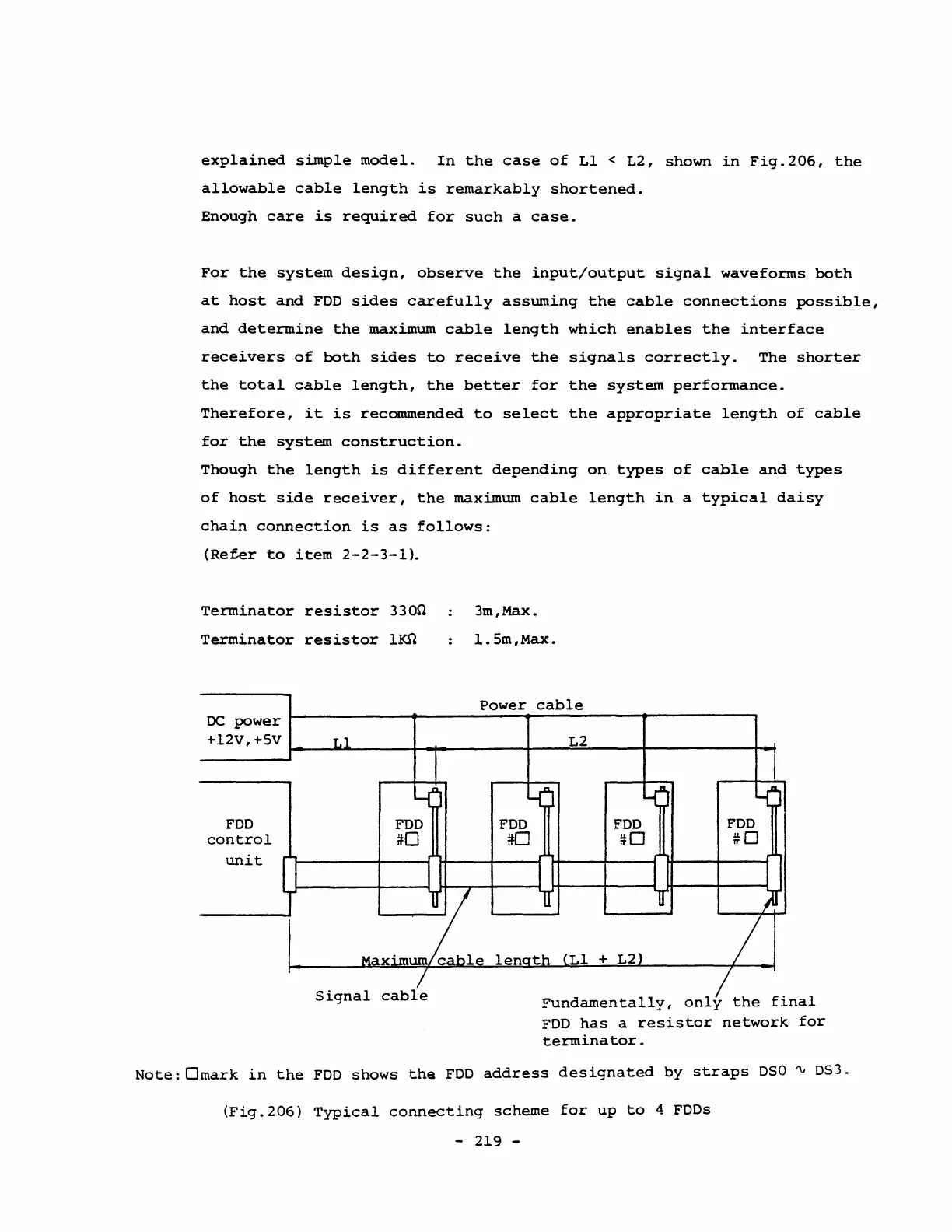
Terminator
resistor
3300
Terminator
resistor
lKn
oe
power
3m,Max.
1.5m,Max.
Power
cable
+12V,+5V L2
~--~~------~~---------+----~~----~----------~~
FDD
control
unit
Signal
cable
Fundamentally,
only
the
final
FDD
has
a
resistor
network
for
terminator.
Note:Omark
in
the
FDD
shows
the
FDD
address
designated
by
straps
DSO
~
OS3.
(Fig.206)
Typical
connecting
scheme
for
up
to
4
FDDs
- 219 -