EasyManua.ls Logo

Teac FD-55 Series - 260

Teac FD-55 Series
73 pages
Print Icon
To Next Page IconTo Next Page
To Previous Page IconTo Previous Page
Loading...
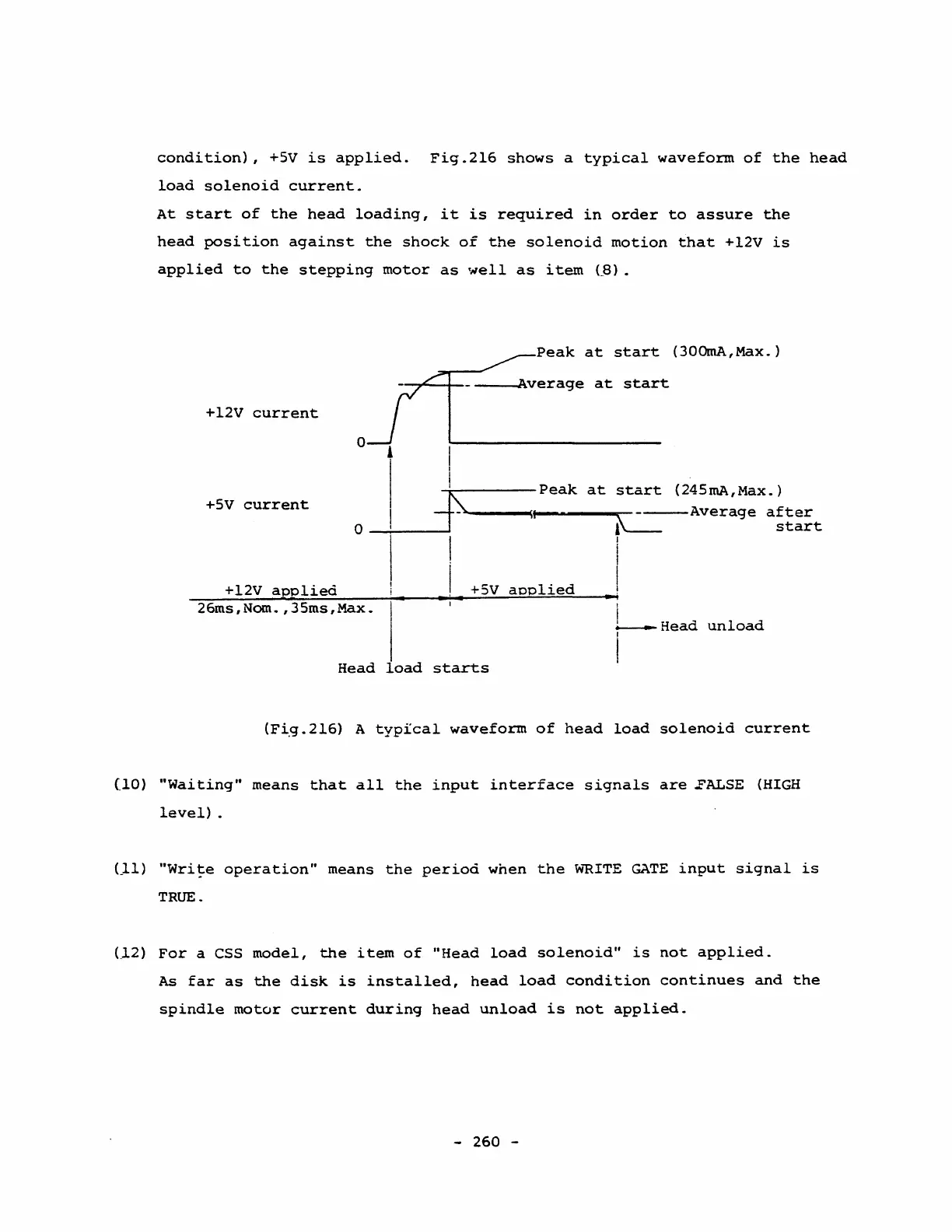
condition),
+5V
is
applied.
Fig.2l6
shows
a
typical
waveform
of
the
head
load
solenoid
current.
At
start
of
the
head
loading,
it
is
required
in
order
to
assure
the
head
position
against
the
shock
of
the
solenoid
motion
that
+l2V
is
applied
to
the
stepping
motor
as
weIl
as
item
(ß).
+l2V
current
+5V
current
+l2V
applie<i
~
__
~~peak
at
start
(300mA,Max.)
O~-~~--+j--
~verage
at
start
I
-,r-----Peak
at
start
(245mA,Max.)
~----
__
~II.
__
~
____
~-----Average
after
o
_i--_~J
~
start
I i
I
+5V
aoplied
I
• ' • • i
26ms,Nom.,35ms,Max.
i
~
Head
unload
Head
load
starts
I
(Fi.g.216)
A
typfcal
waveform
of
head
load
solenoid
current
(lO)
"Waiting"
means
that
all
the
input
interface
signals
are
..FALSE
(HIGH
level)
.
Lll)
"Write
operation"
means
the
period
when
the
w""RITE
GATE
input
signal
is
TRUE.
e12)
For
a CSS
model,
the
item
of
"Head
load
solenoid"
is
not
applied.
As
far
as
the
disk
is
installed,
head
load
condition
continues
and
the
spindle
motor
current
during
head
unload
is
not
applied.
-
260
-