Do you have a question about the Teac SL-D900 and is the answer not in the manual?
Detailed procedures for adjusting the FM and AM tuner sections.
Diagram identifying test points on the Tuner PCB for adjustment.
First exploded view illustrating assembly and component placement.
Second exploded view illustrating assembly and component placement.
Third exploded view illustrating assembly and component placement.
Fourth exploded view illustrating assembly and component placement.
Fifth exploded view illustrating assembly and component placement.
Component list and diagram for the Main Printed Circuit Board.
Component list and diagram for the CD Printed Circuit Board.
Component list and diagram for the Tuner Printed Circuit Board.
Component list and diagram for the Control Printed Circuit Board.
Component lists for Bass VR, Snooze, CD Switch, Phone, Aux, USB PCBs.
Diagram showing connections from the Main PCB to other units.
Diagram showing connections to and from the CD PCB.
List of provided instruction books and their language versions.
List of included remote control units and their color options.
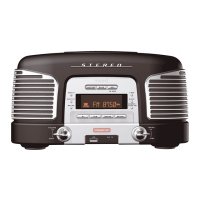
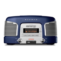
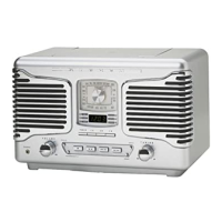
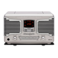
| Brand | Teac |
|---|---|
| Model | SL-D900 |
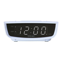
| Category | Clock Radio |
| Language | English |